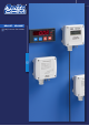
HD402T - HD402ST [ GB ] Pressure Transmitters
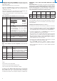
[ GB ] [ GB ] HD402T - HD402ST Description Pressure Transmitters The series of transmitters HD402T... is suitable for measuring relative pressure with respect to atmosphere or differential pressure in the range from 50 Pa to 200 kPa. These transmitters use a silicon piezoresistive sensor with high accuracy and temperature compensation, which has excellent linearity, repeatability and stability over the time.
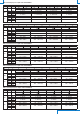
TAB. 1: full scale values and units of measurement Model HD402T1 HD402T2 HD402T3 HD402T4 HD402T5 TAB. 2: resolution Model HD402T1 HD402T2 HD402T3 HD402T4 HD402T5 Pa 50/100/250 250/500/1000 ------- kPa ----2.5/5/10 25/50/100 50/100/200 mbar 0.5/1/2.5 2.5/5/10 25/50/100 250/500/1000 500/1000/2000 mmH2O 5/10/25 25/50/100 ------- inchH2O 0.2/0.4/1 1/2/4 ------- mmHg ----10/25/50 100/250/500 250/500/1000 PSI ----0.4/0.75/1.5 4/7.5/15 10/15/30 Pa 0.1 1 ------- kPa ----0.01 0.1 0.1 mbar 0.001 0.01 0.
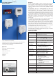
Electrical connections Configuration of the models with analog output (HD402T...) Setting the configuration mode: the transmitter can be configured by using the dip switches on the circuit board or via the serial communication port COM AUX. The choice of the configuration mode is done with the dip switch 1: Power supply • Dip switch 1 = ON ⇒ the configuration set through the dip switches 2...
TAB. 3: measuring ranges for outputs of the model HD402T1 6 OFF ON 2 OFF ON OFF ON OFF ON OFF ON 3 ON OFF OFF ON ON OFF OFF ON Dip switch number 5 4 5 4 OFF OFF ON Pa 0…50.0 Pa 0…100.0 Pa OFF 4 5 4 5 OFF ON ON ON mmH2O 0…5.00 mmH2O 0…10.00 mmH2O inchH2O 0…0.200 inchH2O 0…0.400 inchH2O mbar 0…0.500 mbar 0…1.000 mbar 0…250.0 Pa 0…25.00 mmH2O 0…1.000 inchH2O 0…2.500 mbar -50.0…+50.0 Pa -100.0…+100.0 Pa -5.00…+5.00 mmH2O -10.00…+10.00 mmH2O -0.200…+0.200 inchH2O -0.400…+0.
Configuration via the serial port COM AUX (models with analog output) The configuration set with the serial communication is used by the transmitter only if the dip switch 1 is OFF. In order to modify the settings, please proceed as follows: • Connect the serial COM AUX output of the transmitter to the RS232 port (via the RS27 cable) or USB (via the cable CP27) of the PC. If you use the CP27 cable, install the USB drivers on your PC. Configuration of the models with RS485 Modbus-RTU output (HD402ST...
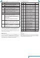
TAB. 10: serial commands (models with RS485 Modbus‑RTU output) Command Description Response time AVGn Set the response time of index n for the measurement n=0 ⇒ 0.
Accessories TAB. 12: MODBUS Holding Registers Register Register Datum number address 101 100 Modbus base address (from 1 to 216) 102 103 Format 16-bit integer Included: • N°1 piece of silicone tubing ø3.2/ø6.4, length 2 m • N°2 plastic fittings HD434T.5 101 Warning: the actual Modbus address of the transmitter is equal to the base address set in this register plus the value set with the dip-switches.
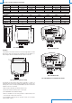
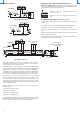
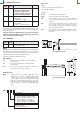
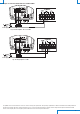
Example of connection with the indicator controller hd9022 8 Power supply Fig. 9: current output 0…20 or 4…20 mA 8 Power supply Fig. 10: voltage output 0…10 Vdc The qualitative level of our instruments is the result of a continuous evolving of the product itself. This may bring to slight differences between what written in the following manual and the instrument you bought. We cannot completely exclude the presence of errors inside the manual, which we apologise for.
MANUFACTURE OF PORTABLE, BENCH TOP AND PROCESS SCIENTIFIC INSTRUMENTS Current and voltage loop transmitters and regulators Temperature - Humidity, Dew point - Pressure - CO, CO2 Air speed - Light - Optical Radiation Acoustics - Vibration Data logger - Data logger wireless Microclimate pH - Conductivity - Dissolved Oxygen - Turbidity Elements for weather stations LAT N° 124 Signatory of EA, IAF and ILAC Mutual Recognition Agreements Temperature - Humidity - Pressure - Air speed Photometry/Radiometry - Acous