
Data Sheet

3
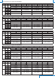
TAB. 1: full scale values and units of measurement
Model
Pa kPa mbar mmH
2
O inchH
2
O mmHg PSI
HD402T1 50/100/250 --- 0.5/1/2.5 5/10/25 0.2/0.4/1 --- ---
HD402T2 250/500/1000 --- 2.5/5/10 25/50/100 1/2/4 --- ---
HD402T3 --- 2.5/5/10 25/50/100 --- --- 10/25/50 0.4/0.75/1.5
HD402T4 --- 25/50/100 250/500/1000 --- --- 100/250/500 4/7.5/15
HD402T5 --- 50/100/200 500/1000/2000 --- --- 250/500/1000 10/15/30
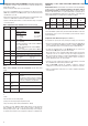
TAB. 2: resolution
Model
Pa kPa mbar mmH
2
O inchH
2
O mmHg PSI
HD402T1 0.1 --- 0.001 0.01 0.001 --- ---
HD402T2 1 --- 0.01 0.1 0.01 --- ---
HD402T3 --- 0.01 0.1 --- --- 0.01 0.001
HD402T4 --- 0.1 1 --- --- 0.1 0.01
HD402T5 --- 0.1 1 --- --- 1 0.01
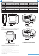
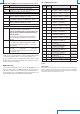
84
80
44
Fig. 1: dimensions (mm)
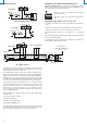
Installation
In any model the sensor and the electronics are housed in a rugged plastic case with
IP67 protection degree. By opening the lid, 3 mm diameter holes are available so to
allow securing the base of the transmitter directly to a panel or to the wall.
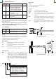
65
50
Ø 3
Ø 3
Fig. 2: fixing holes (dimensions in mm)
The transmitter can be mounted in any position, but typically it is secured on a
vertical wall with the pressure taps facedown. The deviation of the zero due to the
mounting position can be corrected by using CAL ZERO. The procedure for the manual
calibration of the zero is the following:
• make sure that the transmitter is powered at least for 1 hour;
• disconnect both the tubes from the pressure + and – inputs;
• press CAL ZERO until the red LED starts flashing;
• when the red LED turns off, the zeroing procedure is completed and you can
reconnect the tube to the pressure connections.
It is recommended to follow the auto-zero procedure at least once a year under
normal operating conditions.
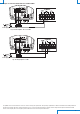
Models with analog output
Models with RS485 output
Fig. 3: CAL ZERO button and configuration dip-switches