
Data Sheet

4
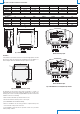
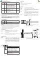
Electrical connections
8
Fig. 4: current analog output
8
Fig. 5: voltage analog output
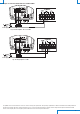
Fig. 6: RS485 connection
In the RS485 connection, the instruments are connected in a sequence through a
shielded cable with twisted pair for signals and a third wire for the common. Line
termination must be set at the two network ends.
The maximum number of devices that can be connected to the RS485 line (Bus)
depends on the load characteristics of the devices to be connected. The RS485 standard
requires that the total load does not exceed 32 unit loads. The load of an HD402ST…
transmitter is equal to ¼ of unit load. If the total load is greater than 32 unit loads, divide
the network into segments and add a signal repeater between a segment and the
successive one. Line termination should be applied at both ends of each segment.
The instrument has a built-in line termination that can be connected or removed
through a short jumper placed next to the terminal block. If the instrument is the
last or the first device of a network group, connect the termination placing the short
jumper between the “RT” and “120ohm” indications. If the instrument is not at the
end of a network group, remove the termination placing the short jumper between
the “RT” and “OPEN” indications.
The cable shield must be connected to both line ends. The cable should have the
following features:
• Characteristic impedance: 120 ohm
• Capacity: less than 50pF/m
• Resistance: less than 100 ohm/km
• Gauge: 0,22 mm
2
(AWG24) at least
The cable maximum length depends on baud rate and cable characteristics. Typically,
the maximum length is 1200 m. The data line must be kept separated from any
power lines in order to prevent interferences on the transmitted signal.
Configuration of the models with analog output (HD402T...)
Setting the configuration mode: the transmitter can be configured by using the dip
switches on the circuit board or via the serial communication port COM AUX. The choice
of the configuration mode is done with the dip switch 1:
• Dip switch 1 = ON ⇒ the configuration set through the dip
switches 2...6 is used
• Dip switch 1 = OFF ⇒ the configuration set via serial port is
used
Configuration by dip switch (models with analog output)
The configuration of the dip switches is used by the transmitter only if the dip switch
1 is ON.
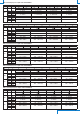
The dip switches 2 and 3 select the low, intermediate or high measuring range.
The dip switches 4 and 5 select one of the four available units in the model.
The dip switch 6 sets the unipolar (0 ... + f.s.) or bipolar (-f.s.....+ f.s.) measuring
range.
A dip switch is OFF when placed down, towards the serial connector. Instead, it is ON if
placed up, towards the DIP SW sign.
The following tables report the measuring range, for each model, corresponding to the
analog outputs according to dip switch positions.
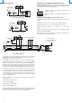
Power supply
Power supply
Power supply
Termination
Termination
Other sensors with RS485
output
PLC, data logger or
RS485/USB or RS485/RS232
converter for PC