
Data Sheet

6
Configuration via the serial port COM AUX (models with analog output)
The configuration set with the serial communication is used by the transmitter only
if the dip switch 1 is OFF.
In order to modify the settings, please proceed as follows:
• Connect the serial COM AUX output of the transmitter to the RS232 port (via the
RS27 cable) or USB (via the cable CP27) of the PC. If you use the CP27 cable, install
the USB drivers on your PC.
• On the PC, launch a program for serial communication (e.g. Hyperterminal), set the
baud rate to 115200 and the communication parameters to 8N1.
• Send the commands given in table 8 to set the measurement range corresponding
to the analog outputs.
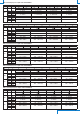
TAB. 8: configuration serial commands (models with analog output)
Command Response Description
Kn & Set the unit of measurement of index n
HD402T1 & HD402T2 HD402T3 &
HD402T4 & HD402T5
n=0 ⇒ Pa n=0 ⇒ kPa
n=1 ⇒ mmH
2
O n=1 ⇒ mmHg
n=2 ⇒ inchH
2
O n=2 ⇒ PSI
n=3 ⇒ mbar n=3 ⇒ mbar
Rn & Set the measuring range of index n
n=0 ⇒ high range
(es. 250 Pa / 25 mmH
2
O / 1 “H
2
O / 2.5 mbar in HD402T1)
n=1 ⇒ intermediate range
(es. 100 Pa / 10 mmH
2
O / 0.4 “H
2
O / 1 mbar in HD402T1)
n=2 ⇒low range
(es. 50 Pa / 5 mmH
2
O / 0.2 “H
2
O / 0.5 mbar in HD402T1)
PU & Set the unipolar measuring range (0…+f.s.)
PB & Set the unipolar measuring range (0…+f.s.)
Sn & Set the response time of index n for the analog outputs
n=0 ⇒ 0.125 s n=1 ⇒ 1 s
n=2 ⇒ 2 s n=4 ⇒ 4 s
U0 & Set the interval 0…20 mA for the analog current output
U1 & Set the interval 4…20 mA for the analog current output
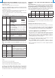
In order to read the settings of the transmitter, send the commands described in
Table 9.
TAB. 9: serial commands to read the configuration (models with analog
output)
Command Response Description
G0 See the example
below
It reads the current configuration of the
transmitter.
If the dip switch 1 is OFF, it returns the configuration
set via the serial port. If the dip switch 1 is set to ON,
it returns the configuration set by dip switch
GF See the example
below
It reads the configuration set by the serial port
GS See the example
below
It reads the configuration set by the dip switch
S? Response time It reads the response time set for the analog
outputs
The commands G0, GF and GS for reading the configuration return a string consisting
of:
• model
• full scale value set for the analog outputs
• polarity of the measuring range (U=unipolar, B=bipolar)
• range of the analog output current (0=0...20mA, 4=4...20 mA)
for example: the string “HD402T2 5.00mbar B40” indicates that the transmitter
model is HD402T2, the full scale set for the analog outputs is 5.00 mbar, the
measuring range is bipolar (-5.00…+5.00 mbar) and the analog current output type
is 4...20 mA. The last character of the string (0 in the example) is a confidential code.
Configuration of the models with RS485 Modbus-RTU output
(HD402ST...)
RS485 Modbus address: each transmitter of the network is univocally identified by
an address between 1 and 247. Transmitters having the same address shall not
be present in the network. The transmitter Modbus address is equal to the sum of
the value set with the dip-switches 2…6 (value settable from 0 to 31) and the value set
with the serial command WA (value settable from 1 to 216, default = 1). By setting a dip-
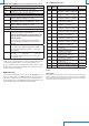
switch to ON (upwards), the following values are added to the address:
Dip-switch
2
Dip-switch
3
Dip-switch
4
Dip-switch
5
Dip-switch
6
ON 16 8 4 2 1
OFF 0 0 0 0 0
Example: if the dip-switches 2 and 4 are set to ON, and the dip-switches 3,5 and 6 are
set to OFF, the value set with the dip-switches is 16+4=20. If the value set with the
serial command WA is 1 (default value), the transmitter Modbus address is 20+1=21.
The dip-switches can be set even if the transmitter is powered, and the change is
effective immediately.
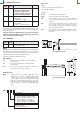
Configuration via the RS485 serial port (models HD402ST…)
The transmitters are preset by the factory. To change the settings, proceed as follows:
• Connect the transmitter RS485 output to the PC RS232 (through a RS485/RS232
converter) or USB (through a RS485/USB converter, for example the RS48 cable)
port. If a RS485/USB converter is used, install in the PC the related USB drivers.
• To enable the configuration mode, set the dip-switch 1 (the one closest to the
terminal block) to ON (upwards), then power the transmitter.
Note: the dip-switch 1 can be changed from OFF to ON even when the instrument
is powered; in this case it is however necessary, after setting the dip-switch to
ON, to press briefly (less than 0.5 seconds) the CAL ZERO button to enable the
configuration mode (the transmitter model information appears on display, if
present). Alternatively, power cycle the transmitter.
• In the PC, run a serial communication software (e.g. Hyperterminal), set the baud
rate to 57600 and the communication parameters to 8N1.
• Send the CAL START command (the command is required to change the
configuratrion; to read the value of the parameters, the command is not required).
• Send the commands given in table 10 to set or read the configuration parameters
of the transmitter.