
Data Sheet


7
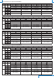
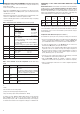
TAB. 10: serial commands (models with RS485 Modbus-RTU output)
Command Description
Response time
AVGn Set the response time of index n for the measurement
n=0 ⇒ 0.125 s n=1 ⇒ 1 s n=2 ⇒ 2 s n=4 ⇒ 4 s
AVG? Reads the response time set for the measurement
Unit of measurement
DU0 Shows pressure in Pa (HD402ST1 and HD402ST2) or kPa
(HD402ST3, HD402ST4 and HD402ST5) on display
DU1 Shows pressure in mmH2O (HD402ST1 and HD402ST2) or
mmHg (HD402ST3, HD402ST4 and HD402ST5) on display
DU2 Shows pressure in inchH
2
O (HD402ST1 and HD402ST2) or PSI
(HD402ST3, HD402ST4 and HD402ST5) on display
DU3 Shows pressure in mbar on display
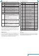
Modbus parameters
WA n…n Sets the Modbus base address to the value n…n
The value must be between 1 and 216 (default = 1)
Warning: the actual Modbus address of the transmitter is equal
to the base address set with this command plus the value set
with the dip-switches.
Note: in the reply to the command, the previous actual address
appears; the new address will appear in the replies to the next
commands.
BAUD r…r Sets the Modbus Baud Rate to the value r…r
The acceptable values are 9600 and 19200 (default = 19200)
If the command is sent without the parameter r…r, the current
setting is obtained
PAR p Sets the Modbus communication parameters of index p
p=O ⇒ 8O1 p=N ⇒ 8N2 p=E ⇒ 8E1
If the command is sent without the index p, the current setting is
obtained (default = 8E1).
Nota: the replies of the transmitters with RS485 Modbus-RTU output always start with
the address of the connected transmitter. For example, sending the AVG2 command
to a transmitter with Modbus address 1, the reply is “001: averaging = 2 sec”.
To exit the configuration mode after sending the CAL START command, send the
CALEND command (the transmitter automatically exits the configuration mode after
5 minutes from the last command sent).
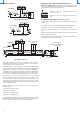
MODBUS-RTU mode
To operate with the Modbus-RTU protocol be sure that the dip-switch 1 (the one
closest to the terminal block) is set to OFF (downwards). The dip-switch can be set
to OFF even if the transmitter is powered, and the change is effective immediately.
The measured values can be read in Modbus-RTU mode by using the 04h function code
(Read Input Registers). Table 11 lists the Modbus Input Registers available:
TAB. 11: MODBUS Input Registers
Register
number
Register
address
Datum Format
4 3 Pressure in tenths of Pa (only HD402ST1) 16-bit integer
5 4 Pressure in Pa
(only HD402ST1, HD402ST2 and HD402ST3)
16-bit integer
6 5 Pressure in daPa
(only HD402ST2, HD402ST3 and HD402ST4)
16-bit integer
7 6 Pressure in hPa
(only HD402ST3, HD402ST4 and HD402ST5)
16-bit integer
8 7 Pressure in kPa
(only HD402ST4 and HD402ST5)
16-bit integer
9 8 Pressure in hundredths of mmH
2
O
(only HD402ST1 and HD402ST2)
16-bit integer
10 9 Pressure in tenths of mmH
2
O
(only HD402ST1, HD402ST2 and HD402ST3)
16-bit integer
11 10 Pressure in mmH
2
O
(only HD402ST2, HD402ST3 and HD402ST4)
16-bit integer
12 11 Pressure in thousandths of inchH
2
O
(only HD402ST1 and HD402ST2)
16-bit integer
13 12 Pressure in hundredths of inchH
2
O
(only HD402ST2 and HD402ST3)
16-bit integer
14 13 Pressure in tenths of inchH
2
O
(only HD402ST3, HD402ST4 and HD402ST5)
16-bit integer
15 14 Pressure in inchH
2
O
(only HD402ST4 and HD402ST5)
16-bit integer
16 15 Pressure in thousandths of mmHg
(only HD402ST2)
16-bit integer
17 16 Pressure in hundredths of mmHg
(only HD402ST2 and HD402ST3)
16-bit integer
18 17 Pressure in tenths of mmHg
(only HD402ST3 and HD402ST4)
16-bit integer
19 18 Pressure in mmHg
(only HD402ST4 and HD402ST5)
16-bit integer
20 19 Pressure in thousandths of PSI
(only HD402ST3)
16-bit integer
21 20 Pressure in hundredths of PSI
(only HD402ST3, HD402ST4 and HD402ST5)
16-bit integer
27 26 Error register 16-bit integer
Reading a register not available for a particular model returns the value -32768
(0x8000).
Error register
The bits of the error register signal, if set to 1, anomalies in the measurement. The bit
0 (the less significant one) indicates a measurement over-range of the transmitter.
The bit 1 indicates whether the measurement is less than the minimum measurable
(under-range). The bits 2 and 3 indicate sensor errors.