
Data Sheet


8
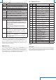
TAB. 12: MODBUS Holding Registers
Register
number
Register
address
Datum Format
101 100 Modbus base address (from 1 to 216)
Warning: the actual Modbus address
of the transmitter is equal to the
base address set in this register plus
the value set with the dip-switches.
16-bit integer
102 101 Modbus Baud Rate
Acceptable values:
3 (⇒ 9600) and 4 (⇒ 19200)
16-bit integer
103 102 Modbus communication parameters
Acceptable values:
1 (⇒ 8N2), 2 (⇒ 8E1) and 4 (⇒ 8O1)
16-bit integer
The Modbus Holding Registers allow setting the same Modbus parameters that can
be set via the serial commands WA, BAUD and PAR. Use the 06h (Write Single Register)
and 03h (Read Holding Registers) function codes to write and read respectively the
content of the registers.
To make the changes of the Holding Registers content active and permanent,
write the hexadecimal value FF00 in the Coil Register number 3 (address 2) by
using the 05h function code (Write Single Coil).
TAB. 13: MODBUS Coils
Register
number
Register
address
Datum
3 2 Activation and permanent storage of the Holding
Registers content changes.
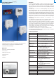
Display
Models with suffix L are equipped with a 4-digit LCD display. In models with LCD option,
the measuring range shown on the display is always bipolar (-f.s.....+f.s.) and related to
the maximum full scale available in the model (the setting of the measuring range in the
models with analog output only affects the behavior of the output).
The measure on the display is updated twice a second.
Error messages:
Undr ⇒ it appears if the measured value is less than the minimum
measurable value
OvEr ⇒ it appears if the measured value exceeds the maximum
measurable value
CAL Error ⇒ it appears at the end of the zero calibration if the maximum offset
value possible to be corrected is exceeded.
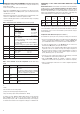
Purchasing codes
HD402T… Pressure relative to the atmosphere or differential pressure
transmitters. For dry air and non-aggressive gases. Barbed
connection diam. 5 mm for hose. RS485 Modbus-RTU output
or analog output at choice between voltage 0...10 V or current
0...20 mA or 4...20 mA. Operating temperature -10...+60 °C.
Power supply: 24Vac or 18...40 Vdc for the models with analog
output, 12...30 Vdc for the models with RS485 Modbus-RTU
output
Accessories
Included:
• N°1 piece of silicone tubing ø3.2/ø6.4, length 2 m
• N°2 plastic fittings HD434T.5
Upon request:
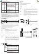
AP3719 Air inlet for square or cylindrical channel.
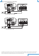
AP3721 Air inlet for cylindrical channel, made of plastic.
RS27 RS232 null-modem serial connection cable with SubD 9-pin
connector on the PC side and 3-pole connector on the side of the
instrument.
CP27 Serial connection cable with USB connector on the PC side and
3-pole connector on the side of the instrument. The cable has
a built-in USB/RS232 converter and it connects the instrument
directly to the USB port of the PC.
RS48 Cable for RS485 connection with built-in USB/RS485 converter.
The cable has USB connector for PC and 3 separate wires for the
instruments.
137
43
Ø 60
Ø42 N° 3x120°
Ø5,5
3
6
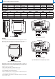
Fig. 7: AP3719 duct probe
135
13 31
Ø 4.5
88
69
6
H
FLOW
L
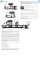
Fig. 8: AP3721 duct probe
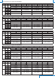
HD402 T - L
L = with LCD display
Nominal full scale (f.s.):
1 = ± 250 Pa / 25 mmH2O / 1 inchH2O / 2,5 mbar
2 = ± 1000 Pa / 100 mmH2O / 4 inchH2O / 10 mbar
3 = ± 10 kPa / 50 mmHg / 1,5 PSI / 100 mbar
4 = ± 100 kPa / 500 mmHg / 15 PSI / 1000 mbar
5 = ± 200 kPa / 1000 mmHg / 30 PSI / 2000 mbar
Output:
Blank = analog output
S = RS485 Modbus-RTU output