
User's Manual


1. MOUNTING THE STAINLESS STEEL BAYONET
MOUNTING BRACKET AND DECK SEAL
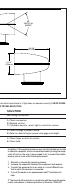
a. Select a location that will allow for clear beam
projection. Searchlight base should be mounted on
level, flat surface.
b. The mounting template should be used to locate the
stainless steel bayonet mounting plate and deck seal
supplied. An xx hole for the 12v supply needs to be
drilled in the location also highlighted on the
mounting template. 4 3/16" mounting holes also need
to be drilled for fixing the light to the deck. It is
recommended that stainless steel mounting bolts be
used with lock washers.
c. Mount light so that the Jabsco name on the base is
facing to the rear.
d. Fasten light in place with XX (XX) #10 x 1" screws
provided or applicable screws for your particular
application.
2. MOUNTING THE SEARCHLIGHT
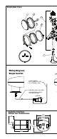
a. Feed the power cables through the central holes in
the bayonet base deck seal. If possible have
someone snake the wires from the inside of the boat
to minimize the amount of cable between the light
and the bayonet base fitting.
b. Place the light on the bayonet base fitting with the
security locking grub screw located at 5 o’clock.
Rotate the light into the bayonet base fitting while
applying reasonable pressure until the security
locking grub screw is at 6 o’clock
c. Using the security locking grub screw key. Lock the
light in place by rotating the security locking grub screw.
3. MOUNTING THE CONTROLLER
a. Select a location, which will allow for fit and
convenient operation of control.
b. Drill one hole (see Panel Cutout Template enclosed)
for running the power supply cables through
c. Run power cables through hole drill, if possible
have someone snake the wires from the inside of the
boat to minimize the amount of cable between the
controller and the mounting surface.
d. Fasten control using the installation kit included
Please note that if this unit is being used to upgrade an exist-
ing searchlight, Jabsco has available to its customers a retro
fit kit that will allow the controller to be seated in a mounting
bracket designed to cover existing holes from previous instal-
lations. This kit number is xxxxx-xxxx.
3: LEARNING MODE PROCEDURE
Note: The controller included with this product was initialized
at the factory to talk with the searchlight it was supplied with.
It is not necessary to conduct this procedure unless adding or
replacing a controller.
a. Disconnect battery power to the receiver.
b. Press and hold the “on/off” button on the controller
while reconnecting power to the searchlight. The
searchlight will turn “on” within (2) seconds.
c. Code synchronization is then complete.
LEARNING ADDITIONAL CONTROLLERSTO THE UNIT
The Jabsco 233SL can support up to (4) separate controllers.
Each time a controller is added to the system or is replaced;
all controllers require re-initialization using the above proce-
dure. Power to the searchlight must be disconnected then
reconnected while pressing the controllers “on/off” button for
each controller added in turn.