User & Technical Manual RZ-01A & RZ-01V Series Rev 2.
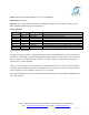
Title: RZ-01A & RZ-01V Air Conditioner User & Technical Manual Department: Engineering Objective: To provide important information for maintenance, diagnostics and advance operations of the DELTA-T RZ-01A & RZ-01V Series Air Conditioners. Revision History: Rev Date Owner Description of Changes 1.4 1.5 1.6 1.7 1.8 1.9 2.0 2.1 01-16-13 02-05-13 02-21-13 04-26-13 08-08-13 01-15-14 03-17-14 08-04-14 B. Slotnick B. Slotnick B. Slotnick B. Slotnick B. Slotnick B. Slotnick B. Slotnick B.
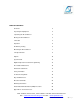
TABLE OF CONTENTS Overview 4 Inspecting the Equipment 4 Unpacking the Air Conditioner 4 Moving the Air Conditioner 5 Unit Label 5 Operation 6 Preliminary Testing 6 Mounting the Air Conditioner 7 Unit Specifications 8 Options 10 System Faults 13 Digital Temperature Controller Programming 13 Preventative Maintenance 16 Field Serviceable Parts 17 Safety Information 17 Troubleshooting Guide 18 Physical Dimensions 21 Electrical Schematic 23 Warranty Information 24 Return Mat
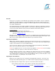
Overview Thank you for your purchase of the DELTA-T Special Purpose Air Conditioner. Our air conditioning equipment is carefully designed to cool and dehumidify the air in electronic component enclosures. ISC has designed air conditioners for all types of electronic equipment enclosures providing capacity from 1,000 to 20,000 BTUH. This manual will guide you through the installation, maintenance, diagnostics and advance operations of the RZ-01A & RZ-01V Series Air Conditioners.
Note: Shipping without being strapped to the pallet may result in tipping and damage, this will void the warranty. Moving the Air Conditioners Read this section completely before running or installing your DELTA-T air conditioning equipment. Note: You will need to perform a Preliminary Test before mounting the air conditioner. Refer to the Preliminary Test section in this manual for instructions on how to run this test.
Operation DELTA-T air conditioners will lower (or increase as necessary) the temperature inside an enclosure to ensure its proper operational temperature. Our air conditioners, when sized properly, will provide cooling or heating automatically controlled by the temperature digital controller. DELTA-T air conditioners operate as a “closed loop” system with no exposure or introduction of outside air.
The condenser fan is controlled by the refrigerant high heat pressure and will turn on later when the operating pressure builds up. This feature allows low ambient operation and reduces current inrush at initial power on. Run the air conditioner for 15 minutes; during this time the condenser fan will turn on after the condenser coil warms up. Note: Ambient Temperature must be at least 75°F.
CAUTION If mounting the air conditioner to the enclosure door, confirm with the enclosure manufacturer that the door’s hinges will support the air conditioner’s added weight (see equipment specifications). Ensure that when the door is fully open that the enclosure will not topple over due to the off-center load. Unit Specifications The following tables provide electrical and refrigeration specifications for the RZ-01 Series Air Conditioners.
RZ-01V Series Nominal Capacity Rating: 1,500 BTUH Standard Maximum Ambient: 125°F Unit Weight: 57lbs (120/230VAC) Operating Voltage Range Inrush Current (Start Up Current) Loading Current (Running Current) SCCR (Short Circuit Current Rating) Recommended Fuse Selection KVA Rating (Volts) (Amps) (Amps) (Amps) (K-Watts) RZ-01V-126 110-120 22.69 3.89 *2 RZ-01V-236 220-240 13.77 2.
Options The RZ-01A & RZ-01V Series Air Conditioners may be ordered with the following options. Review the list below for the specifications and functions of the option(s) that apply to your unit. Low Ambient This option consists of circuitry to protect the compressor in a low ambient temperature environment. The low ambient package is designed to provide an optimum constant low current in the compressor motor during the non cooling state.
Celsius Programming Celsius Programming option allows the user to control the DELTA-T Air Conditioner in SI units. This feature can be programmed into the digital temperature controller at time of manufacturing. External Heat Output This option allows you to add an external heater to be located anywhere in your enclosure. These external heaters are ideal for focusing on individual sections of the enclosure without having a large capacity Built-in Heater.
Ethernet/IP Controller Output This option provides the ability to communicate with the DELTA-T Air Conditioner controller via the Ethernet/IP protocol. You can monitor and control all settings from a remote location with a PLC. Full specifications will be provided with this option. For full details refer to the Ethernet/IP Option Specifications included with the Air Conditioner.
System Faults If any of the critical control parameters exceed limits, the compressor is turned off and an alarm condition is indicated on the front panel.
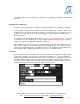
HOW TO ACCESS HIDDEN MENU 1…….. 1. Enter the Programming mode by pressing the SET + DOWN arrow keys simultaneously for 3 seconds. The “F” LED starts blinking. 2. Select the required parameter by pressing the UP or DOWN arrow key. Press the SET key to display its value. 3. Use the UP or DOWN arrow key to change its value. 4. Press SET to store the new value and move to the following parameter. To exit: Press SET + UP arrow keys or wait 15 seconds without pressing a key.
Function Operation Parameter Menu Location Factory Default Operating Range Unit Auxiliary Differential Heater or Dry Contact Hysteresis *1 Shy Hidden Menu 2 3 1 - 45 °F Maximum Temperature Alarm Minimum Temperature Alarm Alerts with “HA” when maximum temperature has been exceeded Alerts with “LA” when minimum temperature has been exceeded ALU Hidden Menu 2 105 45 - 302 °F ALL Hidden Menu 2 45 -67 - 105 °F *1 Note: When both Heater and Dry Contact options are included, these paramet
Preventative Maintenance Air conditioners require regular cleaning of the condenser air inlet filter. Wash filter often if washable using proper cleaning compound and back flushing the dirt out, or replace if not washable whenever it appears physically dirty. Restriction to the flow of air over the condenser coil will degrade the performance of the equipment, cause it to overheat, reduce cooling and can damage the compressor.
Troubleshooting Guide The following guide provides a flow chart to identify a problem, determine the root cause and identify the action needed to correct an issue.
Unit Not Cooling Is Compressor On? YES Is evaporator Fan on? Measure Temperature at Evaporator & Verify Heat Load Requirements. Is unit capacity adequate for internal head load? Possible low refrigerant. YES NO NO Check for faulty 3 evaporator fan Check Setpoint.
Single or Multiple Codes? Flashing Error Codes P1 / P2 combination flashing? 2+ Potential bad connection. Check green connector behind controller. YES NO 1 CA Refer to Alarm Signals in Digital Temperature Controller Programming Section Check Low Pressure Switch Connections and Verify Pressure switch is closed. Use 3 meter. YES NO P1 or P2 YES Check probe connections, potential faulty probe.
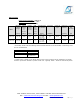
Water overflow / excessive Check drain, is it plugged? NO Is Air Conditioner sealed against enclosure properly, tightly sealed and door closed? NO Ensure air tight seal between air conditioner and enclosure. Make sure door is closed. YES YES Clean condensate pan and drain; add 1 tbsp bleach to upper pan monthly to kill mold Contact Customer Service Physical Dimensions 4421 Tradition Trail ● Plano, Texas 75093 ● 972-964-2700 ● 800-836-7472 URL: www.iscenclosurecooling.com ● Email: iscinfo@iscsales.
THIS PAGE IS INTENTIONALLY LEFT BLANK 4421 Tradition Trail ● Plano, Texas 75093 ● 972-964-2700 ● 800-836-7472 URL: www.iscenclosurecooling.com ● Email: iscinfo@iscsales.com SP-ENG-210-100-09 Rev 2.
Electrical Schematics System Schematic Digital Controller Schematic Note: Schematics apply to all voltages; optional accessories wiring not provided in this document. If you require electrical schematic with options contact our technical support and provide your model number. Warranty Information 4421 Tradition Trail ● Plano, Texas 75093 ● 972-964-2700 ● 800-836-7472 URL: www.iscenclosurecooling.com ● Email: iscinfo@iscsales.com SP-ENG-210-100-09 Rev 2.
ISC products are warranted to be free of defects in workmanship, materials and components. The warranty period applies from date of shipment for one year.
All returns require a Return Material Authorization (RMA) number for warranty or non-warranty repair, rotation of stock, damage or any other reason. IMPORTANT Returns without an RMA number will be refused and returned. Improper packaging may void warranty. Air Conditioners shipped laying down will void the warranty. Collect shipments will be refused.
Appendix A Phoenix Contact Power Connector Instructions Scope: Instructions for connecting power wires to air conditioners equipped with a “Phoenix Contact” power connector. 1 - Remove cover from chassis using T25 Torx bit. 2 - Push both orange tabs in to release male connector and pull out for wire connection. NOTE: If using stranded wires, it may be difficult to insert into the receptacles without releasing the spring tension as described below in the removal instructions.