^1 HARDWARE REFERENCE MANUAL ^2 16-Axis MACRO CPU Preliminary Documentation ^3 16-Axis MACRO CPU ^4 4Ax-603719-xHxx ^5 April 21, 2010 Single Source Machine Control Power // Flexibility // Ease of Use 21314 Lassen Street Chatsworth, CA 91311 // Tel. (818) 998-2095 Fax. (818) 998-7807 // www.deltatau.
Copyright Information © 2010 Delta Tau Data Systems, Inc. All rights reserved. This document is furnished for the customers of Delta Tau Data Systems, Inc. Other uses are unauthorized without written permission of Delta Tau Data Systems, Inc. Information contained in this manual may be updated from time-to-time due to product improvements, etc., and may not conform in every respect to former issues. To report errors or inconsistencies, call or email: Delta Tau Data Systems, Inc.
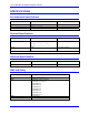
REVISION HISTORY REV. DESCRIPTION DATE CHG APPVD 1 ADDED CE DECLARATION OF CONFORMITY 08/23/06 CP S. FIERRO 2 ADDED INDICATOR LEDs, PP.11-12 04/21/10 CP S.
16-Axis MACRO CPU Hardware Reference Manual Table of Contents INTRODUCTION .....................................................................................................................................................1 3U Product Configurations (General Description)..................................................................................................2 Configuration ............................................................................................................................
16-Axis MACRO CPU Hardware Reference Manual ii Table of Contents
16-Axis MACRO CPU Hardware Reference Manual INTRODUCTION The 16-Axis MACRO CPU board is the processor and MACRO interface board used in a 3U MACRO Station (in either UMAC MACRO or MACRO Stack configuration). Note: There are three documents that describe the operation of 3U MACRO Station products: • UMAC System Manual (General Product Overview) • MACRO 16 Station User’s Manual • MACRO 16 Station Software Reference This manual describes the interfaces and physical hardware that is used on the 3U MACRO CPU.
16-Axis MACRO CPU Hardware Reference Manual UMAC MACRO – In this configuration (once called Pack) the 3U-format boards are put together to communicate through a backplane bus called the UBUS. All boards are installed in a Euro-card rack. In this configuration, all 3U-format boards or modules can be installed or withdrawn from the pack individually, providing ease of installation, debugging, and repair.
16-Axis MACRO CPU Hardware Reference Manual Configuration The purchase of the 3U 16-Axis MACRO CPU board provides a 3U-format (100mm x 160mm) board with a DSP processor, MACRO ring circuitry, and a backplane connector through which other 3U-format boards can be connected by means of a UBUS passive-backplane board. The 3U 16-Axis MACRO CPU can be purchased in two physical configurations, distinguished by part number prefix: • 300-603719-10x provides the 16-Axis MACRO CPU board without a front plate.
16-Axis MACRO CPU Hardware Reference Manual SPECIFICATIONS Environmental Specifications Description Specification Notes Operating Temperature Storage Temperature Humidity 0°C to 45°C, -25°C to 70°C 10% to 95 % non-condensing Physical Specifications Description Specification Dimensions Length: 16.256 cm Notes (6.4 in.) Height: 10 cm (3.94 in.) Width: 2.03 cm (0.8 Weight in.) 188 g Front Plate included The width is the width of the front plate.
16-Axis MACRO CPU Hardware Reference Manual HARDWARE SETUP The hardware setup of the 3U 16-Axis MACRO CPU Board consists of the setting of two rotary switches, the setting of several E-point jumpers on each board, followed by power supply and signal connections. Note: E-Point Jumper numbers are shown in white ink on the legend of each board.
16-Axis MACRO CPU Hardware Reference Manual Board Connections The connection of Compact MACRO Station to other stations on the MACRO ring is achieved by connecting the output connector of the Compact MACRO Station to the input connector of the next station, and by connecting the output connector of the previous station to the input connector of the Compact MACRO Station. There must be a completely connected ring with all stations powered up, for any communications to occur on the ring.
16-Axis MACRO CPU Hardware Reference Manual Hardware Re-initialization MACRO hardware re-initialization to factory defaults is enabled when the SW1 setting is set to 15 or F (hexadecimal) and the power is cycled at the MACRO Station. The only time to use a hardware reinitialization to factory defaults with the MACRO Station would be if the MACRO Station always powers up with a watchdog (typically if the ring clock at the Ultralite is different from the ring clock at the MACRO Station).
16-Axis MACRO CPU Hardware Reference Manual 8 Hardware Setup
16-Axis MACRO CPU Hardware Reference Manual JUMPER AND SWITCH CONFIGURATIONS Layout Jumper Descriptions E1: Watchdog Timer Disable Jumper Type 2-Pin Description Default Remove jumper to enable Watchdog Timer. Jump pins 1 and 2 to disable Watchdog Timer (for test purposes only). not jumpered E2: CPU Mode Operation Jumper Type 3-Pin Description Default Jump pins 1 and 2 for firmware download through serial port. Jump pins 2 and 3 for normal operation.
-Axis MACRO CPU Hardware Reference Manual Switch Configurations SW1: MACRO Slave Node Configure SW1 Select I/O Nodes Enabled Servo Nodes Enabled Node Servo IC Base Address Nodes Enabled Y:I181…188 0 0 4 1 0 4 2 3 4 5 6 0 0 0 0 0 2 2 2 2 6 7 0 8 $8000,$8008, $8010,$8018 $8000,$8008, $8010,$8018 $8000,$8008 $8000,$8008 $8000,$8008 $8000,$8008 $8000,$8008, $8010,$8018, $8040,$8048 $8000,$8008, $8010,$8018, $8040,$8058, $8050,$8058 I181, I182, I183, I184 I185, I186, I187, I188 I181, I182 I
16-Axis MACRO CPU Hardware Reference Manual CHARACTER DISPLAY AND LEDS The MACRO Station has a single hexadecimal character display on the CPU/Interface Board that provides useful information as to the status of the station. The display indicates how many motors are activated and displays certain types of failures that might occur. One unique feature on the display is the LED dot in the bottom left corner. When this LED is illuminated, that means 8 must be added to the number being displayed.
16-Axis MACRO CPU Hardware Reference Manual There are also three LEDs on the front panel (left adjacent to the seven-segment LED display) indicating the following: D7 (PW) – Green Power LED indicating the +5V is on and OK. D8 (WD) – Red WATCHDOG LED indicating a watchdog condition.
16-Axis MACRO CPU Hardware Reference Manual CONNECTOR PINOUTS The schematic circuits shown in this section are for interface reference only. Subtle differences may exist between the circuits shown here and the actual hardware used. The connectors on the 16-Axis MACRO CPU are found on both the main (603719-10x) board and on an I/O daughter card (603720-10x) that plugs into the main board.
16-Axis MACRO CPU Hardware Reference Manual TB1: (JPWR) 4-Pin Terminal Block (Location B-4) Pin # Symbol Function 1 2 3 4 GND +5V +15V -15V Common Input Input Input Description Reference Voltage Positive Supply Voltage Positive Supply Voltage Negative Supply Voltage Notes Supplies all PMAC digital circuits +12V to +15V; used for on-board analog -12 to –15V; used for on-board analog TB2: (JWD) 4-Pin Terminal Block Pin # Symbol Function 1 2 3 4 NC COM NO COM Output Input Output Input 14 Desc
16-Axis MACRO CPU Hardware Reference Manual P1: UBUS Interface Connector (96 pin Euro Connector at F-1, 2, 3, 4) Front View on MACRO CPU Card Pin # 1. 2. Row A Row B Row C 1 +5Vdc +5Vdc +5Vdc 2 GND GND GND 3 BD01 DAT0 BD00 4 BD03 SEL0 BD02 5 BD05 DAT1 BD04 6 BD07 SEL1 BD06 7 BD09 DAT2 BD08 8 BD11 SEL2 BD10 9 BD13 DAT3 BD12 10 BD15 SEL3 BD14 11 BD17 DAT4 BD16 12 BD19 SEL4 BD18 13 BD21 DAT5 BD20 14 BD23 SEL5 BD22 15 BS1 (GND) DAT6 BS0 (GND) 16 BA01 SEL6 BA00 17 BA03 DAT7 BA02 18 BX/Y SEL7 BA04 (n.c.
16-Axis MACRO CPU Hardware Reference Manual Daughter Board Connections (603720) J2 (JDISP) Display Connector Pin # Symbol Function Description Notes 1 +5V Output Logic Power Power supply out 2 GND Common Logic Ground 3 RS Output Read strobe TTL signal out 4 Vee Output Contrast adjust VEE 0 to +5Vdc * 5 E Output Display enable High is enable 6 R/W Output Read or write TTL signal out 7 DB1 Output Display data1 8 DB0 Output Display data0 9 DB3 Output Display data3 10 DB2 Output Display data2 11 DB5 Outpu
16-Axis MACRO CPU Hardware Reference Manual J4: (JRS232) Serial Port Connector DB9-pin Female Pin # Symbol Function 1 2 3 4 5 6 7 8 9 N.C. TXD/ RXD/ DSR GND DTR CTS RTS N.C.
16-Axis MACRO CPU Hardware Reference Manual 18 Connector Pinouts
16-Axis MACRO CPU Hardware Reference Manual HARDWARE MEMORY MAP The values in this table represent the hardware locations associated with register-based transactions that occur in the 16-Axis MACRO CPU.
16-Axis MACRO CPU Hardware Reference Manual 20 Hardware Memory Map
16-Axis MACRO CPU Hardware Reference Manual ACCESSORIES Both the Turbo and the 16-Axis MACRO CPU boards can support either the Stack or the UMAC configuration. The systems are configured modularly with the selection of a series of accessory boards, some appropriate for the Stack and some appropriate for the UMAC. These accessories are listed here. Each has its own manual with detailed descriptions.
16-Axis MACRO CPU Hardware Reference Manual 16-Axis MACRO CPU Board Options Board must be ordered with either Option A or Option C.
16-Axis MACRO CPU Hardware Reference Manual DECLARATION OF CONFORMITY Application of Council Directive: 89/336/EEC, 72/23/EEC Manufacturers Name: Manufacturers Address: Delta Tau Data Systems, Inc. 21314 Lassen Street Chatsworth, CA 91311 USA We, Delta Tau Data Systems, Inc.