
Reference Manual

16-Axis MACRO CPU Software Reference Manual
16-Axis MACRO Station MI-Variable Reference 13
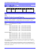
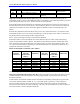
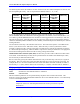
MS{anynode},MI91 - MI98 Phase Interrupt 24 Bit Data Copy
Range: $00000000 - $FFFFFFFF
Units: Individual bits
Hex Digit #
1 2 3 4 5 6 7 8 9 10 11 12
Contents
From $00
= Y: 24bit
$80 = X:
24bit
From Register Address To $00 =
Y: 24bit
$80 = X:
24bit
To Register Address
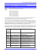
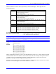
MS{anynode},MI99 (Reserved for Future Use)
Range: 0
Units:
Default: 0
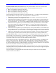
MACRO IC Position Processing MI-Variables
Each MACRO IC (0 and 1) has its own set of these variables. Therefore, they are accessed through their
MACRO IC. For example, MS0,MI101 accesses MACRO IC 0’s MI101 and MS16,MI101 accesses
MACRO IC 1’s MI101. MACRO IC 1’s variables can be accessed can be accessed through MACRO IC
0 by adding 1000 to the MI variable. For example, MS0,MI1101 accesses MACRO IC 1’s MI101.
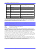
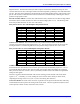
MS{anynode},MI101-MI108 Ongoing Position Source Address
Range: $0000 - $FFFF
Units: 16-Axis MACRO Station “X” Addresses
Default MACRO IC 0:
MI101 (1
st
motor node: Node 0): $0010 {1
st
line of encoder conversion table}
MI102 (2
nd
motor node: Node 1): $0011 {2
nd
line of encoder conversion table}
MI103 (3
rd
motor node: Node 4): $0012 {3
rd
line of encoder conversion table}
MI104 (4
th
motor node: Node 5): $0013 {4
th
line of encoder conversion table}
MI105 (5
th
motor node: Node 8): $0014 {5
th
line of encoder conversion table}
MI106 (6
th
motor node: Node 9): $0015 {6
th
line of encoder conversion table}
MI107 (7
th
motor node: Node 12): $0016 {7
th
line of encoder conversion table}
MI108 (8
th
motor node: Node 13): $0017 {8
th
line of encoder conversion table}
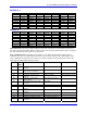
Default MACRO IC 1:
MI101 (1
st
motor node: Node 0): $0090 {1
st
line of encoder conversion table}
MI102 (2
nd
motor node: Node 1): $0091 {2
nd
line of encoder conversion table}
MI103 (3
rd
motor node: Node 4): $0092 {3
rd
line of encoder conversion table}
MI104 (4
th
motor node: Node 5): $0093 {4
th
line of encoder conversion table}
MI105 (5
th
motor node: Node 8): $0094 {5
th
line of encoder conversion table}
MI106 (6
th
motor node: Node 9): $0095 {6
th
line of encoder conversion table}
MI107 (7
th
motor node: Node 12): $0096 {7
th
line of encoder conversion table}
MI108 (8
th
motor node: Node 13): $0097 {8
th
line of encoder conversion table}
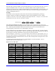
MI101 through MI108 (MI10x) determine what registers are used for feedback for the eight possible
motor nodes (MI10x controls the xth motor node, which usually corresponds to Motor x on PMAC) on a
16-Axis MACRO Station.
For each active motor node, the value in the specified register is copied into the 24-bit position feedback
MACRO register. Typically, the addresses specified are those from the 16-Axis MACRO Station’s
encoder conversion table, at Station registers X:$0010 to X:$002F, corresponding to Station MI-variables
MI120 to MI151, respectively.