
Reference Manual

16-Axis MACRO CPU Software Reference Manual
16-Axis MACRO Station MI-Variable Reference 21
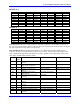
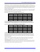
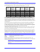
The following table shows the addresses for each channel on the ACC-24E2x backplane axis boards, and
the corresponding ECT entry. The ‘m’ represents the method, either ‘9’, ‘A’, or ‘B’.
Machine
Interface
Channel #
16-Axis
MACRO
Station Base
Address
Conversion
Table Entry
Machine
Interface
Channel #
16-Axis
MACRO
Station Base
Address
Conversion
Table Entry
1 $8000 $m08000 9 $9000 $m09000
2 $8008 $m08008 10 $9008 $m09008
3 $8010 $m08010 11 $9010 $m09010
4 $8018 $m08018 12 $9018 $m09018
5 $8040 $m08040 13 $9040 $m09040
6 $8048 $m08048 14 $9048 $m09048
7 $8050 $m08050 15 $9050 $m09050
8 $8058 $m08058 16 $9058 $m09058
In use, the method byte is changed as needed by setting of the MI-variable. It is set to $90 (e.g.
MI129=$908808) before the calculations of the triggered move are started, to freeze the time base. It is
set to $B0 (e.g. MI129=$B08808) after the calculations of the triggered move are finished, to “arm” the
time base for the trigger. When the Table sees the trigger (the capture trigger for the machine interface
channel as defined by MI912 and MI913 for the channel), it automatically sets the method byte to $A0 for
running time base.
The second line in the entry is the time-base scale factor. The result value equals 2 * Time-Base-Scale-
Factor * (New Source Value - Old Source Value). When this entry is used to synchronize a motion
program to a master encoder, creating an electronic cam function, this scale factor should be set equal to
2
17
/ Real-Time-Input-Frequency, where the RTIF is expressed in counts per millisecond. The program is
then written assuming that the master encoder is always putting out this RTIF.
Addition/Subtraction of Entries ($E0, $E8): The $Ex entry is used to add or subtract two other entries
in the Table. If the method byte is $E0, the two specified entries are added. If the method byte is $E8,
the second entry is subtracted from the first.
Bits 0-7 of the entry specify the address offset from this entry to the first entry to be used, as a signed 8-
bit quantity. Bits 8-15 of the entry specify the offset from this entry to the second entry to be used. For
example, MI131 is to be used to subtract the result values with MI121 from that of MI120, the offset to
the first entry is -11 ($F5), and the offset to the second entry is -10 ($F6). Therefore MI131=$E8F6F5.
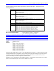
MS{anynode},MI152 - MI153 Phase-Clock Latched I/O
Range: $000000000000 - $FFFFFFFFFFFF
Units: Extended 16-Axis MACRO Station Y Addresses
Default: $000000000000
MI152 and MI153 permit the use of inputs latched by the phase clock on Station I/O boards. This
function is used to get reliable parallel-data feedback on the 16-Axis MACRO Station. It is useful mainly
on ACC-14E backplane boards.
Note:
Jumper E2 on the ACC-14E backplane board must connect pins 2 and 3 to permit
this function.