
User's Manual
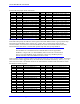
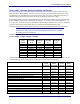
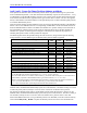
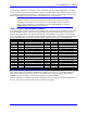

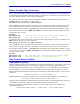
Table Of Contents
- 16-Axis MACRO Slave Station Binding to a MACRO Master
- Mapping Servo Channels to Servo Node
- Mapping Motor Node Registers
- Mapping Motor Function Registers to Node Registers
- Mapping of General Purpose I/O
- UMAC (Pack) Configuration
- I/O Accessory Boards
- Auto Configuration and Identification of UMAC (Pack) Boards
- UMAC (Pack) Interface/Breakout Boards
- MACRO Ring Rules
- I7: Phase Cycle Extension
- I19: Clock Source I-Variable Number
- Turbo PMAC2 Ultralite: I6800 and I6801
- UMAC Turbo
- Notes on Servo Clock
- I6840: MACRO IC 0 Master Configuration
- I6890/I6940/I6990: MACRO IC 1/2/3 Master Configuration
- I6841/I6891/I6941/I6991: MACRO IC 0/1/2/3 Node Activation Control
- I70/I72/I74/I76: MACRO IC 0/1/2/3 Node Auxiliary Function Enable
- I71/I73/I75/I77: MACRO IC 0/1/2/3 Node Protocol Type Control
- I78: MACRO Master/Slave Auxiliary Communications Timeout
- I79: MACRO Master/Master Auxiliary Communications Timeout
- I80, I81, I82: MACRO Ring Check Period and Limits
- Ixx01: Commutation Enable
- Ixx02: Command Output Address
- Ixx03, Ixx04: Feedback Address
- Ixx10, Ixx95: Absolute Position Address and Format
- Ixx25, Ixx24: Flag Address and Mode
- Ixx70, Ixx71: Commutation Cycle Size
- Ixx75: Absolute Phase Position Offset
- Ixx81, Ixx91: Power-On Phase Position Address and Mode
- Ixx82: Current Loop Feedback Address
- Ixx83: Commutation Feedback Address
- Ring Update Frequency
- Station Servo Clock Frequency
- MACRO IC 0
- MACRO IC 1
- MACRO IC 0
- MACRO IC 1
- Channels 1-4 (First 4-Axis Board)
- Channels 5-8 (Second 4-Axis Board)
- On Board Auxiliary Channels (Handwheel/Pulse and Direction)
- Incremental Digital Encoder Feedback
- Analog Encoder Feedback
- Resolver Feedback
- MLDT Feedback
- 12-Bit A/D Converter Feedback
- 14E Parallel Feedback
- MI17 Amplifier Fault Disable Control
- MI18 Amplifier Fault Polarity Control
- MI10x Position Feedback Address
- MI11x Power-On Position Feedback Address
- MI16x Power-On MLDT Excitation Value
- MI975 I/O Node Enable
- MI19 I/O Transfer Period
- Bi-Directional I/O Transfer Control
- Uni-Directional I/O Transfer Control
- Setting the Trigger Condition
- Using for Homing
- Using in User Program
- Setting up for a Single Pulse Output
- Setting up for Multiple Pulse Outputs
- How to Enable and Disable MACRO ASCII Communication Mode
- The Ring Order Method
- Example: Read Using MM-Variables – Actual Encoder
- Example: Read DAC Output from Servo IC Card
- Example: Monitor Up/Down Counter from Servo IC Card
- Example: Write to DACnB on Servo IC Card
- Example: Read Using MI198 and MI199 – Direct Hal
- Example: Read Using MI198 and MI199 – Actual DAC
16-Axis MACRO CPU User Manual
Turbo PMAC2 Software Setup for MACRO Station 29
The following table contains the default Ixx83 values for Turbo PMAC2 Ultralite boards, listing the
addresses of the position feedback registers for each MACRO servo node.
Ixx83 Value Register Ixx83 Value Register
I183 $078420 MACRO IC 0 Node 0 Reg. 0 I1783 $07A420 MACRO IC 2 Node 0 Reg. 0
I283 $078424 MACRO IC 0 Node 1 Reg. 0 I1883 $07A424 MACRO IC 2 Node 1 Reg. 0
I383 $078428 MACRO IC 0 Node 4 Reg. 0 I1983 $07A428 MACRO IC 2 Node 4 Reg. 0
I483 $07842C MACRO IC 0 Node 5 Reg. 0 I2083 $07A42C MACRO IC 2 Node 5 Reg. 0
I583 $078430 MACRO IC 0 Node 8 Reg. 0 I2183 $07A430 MACRO IC 2 Node 8 Reg. 0
I683 $078434 MACRO IC 0 Node 9 Reg. 0 I2283 $07A434 MACRO IC 2 Node 9 Reg. 0
I783 $078438 MACRO IC 0 Node 12 Reg. 0 I2383 $07A438 MACRO IC 2 Node 12 Reg. 0
I883 $07843C MACRO IC 0 Node 13 Reg. 0 I2483 $07A43C MACRO IC 2 Node 13 Reg. 0
I983 $079420 MACRO IC 1 Node 0 Reg. 0 I2583 $07B420 MACRO IC 3 Node 0 Reg. 0
I1083 $079424 MACRO IC 1 Node 1 Reg. 0 I2683 $07B424 MACRO IC 3 Node 1 Reg. 0
I1183 $079428 MACRO IC 1 Node 4 Reg. 0 I2783 $07B428 MACRO IC 3 Node 4 Reg. 0
I1283 $07942C MACRO IC 1 Node 5 Reg. 0 I2883 $07B42C MACRO IC 3 Node 5 Reg. 0
I1383 $079430 MACRO IC 1 Node 8 Reg. 0 I2983 $07B430 MACRO IC 3 Node 8 Reg. 0
I1483 $079434 MACRO IC 1 Node 9 Reg. 0 I3083 $07B434 MACRO IC 3 Node 9 Reg. 0
I1583 $079438 MACRO IC 1 Node 12 Reg. 0 I3183 $07B438 MACRO IC 3 Node 12 Reg. 0
I1683 $07943C MACRO IC 1 Node 13 Reg. 0 I3283 $07B43C MACRO IC 3 Node 13 Reg. 0
Because these are all Y addresses, bit 1 of Ixx01 must be set to 1. With bit 0 of Ixx01 set to 1 to enable
commutation, the net value of Ixx01 is 3.