
User's Manual
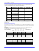
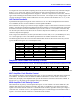
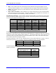
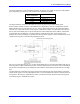
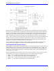
Table Of Contents
- 16-Axis MACRO Slave Station Binding to a MACRO Master
- Mapping Servo Channels to Servo Node
- Mapping Motor Node Registers
- Mapping Motor Function Registers to Node Registers
- Mapping of General Purpose I/O
- UMAC (Pack) Configuration
- I/O Accessory Boards
- Auto Configuration and Identification of UMAC (Pack) Boards
- UMAC (Pack) Interface/Breakout Boards
- MACRO Ring Rules
- I7: Phase Cycle Extension
- I19: Clock Source I-Variable Number
- Turbo PMAC2 Ultralite: I6800 and I6801
- UMAC Turbo
- Notes on Servo Clock
- I6840: MACRO IC 0 Master Configuration
- I6890/I6940/I6990: MACRO IC 1/2/3 Master Configuration
- I6841/I6891/I6941/I6991: MACRO IC 0/1/2/3 Node Activation Control
- I70/I72/I74/I76: MACRO IC 0/1/2/3 Node Auxiliary Function Enable
- I71/I73/I75/I77: MACRO IC 0/1/2/3 Node Protocol Type Control
- I78: MACRO Master/Slave Auxiliary Communications Timeout
- I79: MACRO Master/Master Auxiliary Communications Timeout
- I80, I81, I82: MACRO Ring Check Period and Limits
- Ixx01: Commutation Enable
- Ixx02: Command Output Address
- Ixx03, Ixx04: Feedback Address
- Ixx10, Ixx95: Absolute Position Address and Format
- Ixx25, Ixx24: Flag Address and Mode
- Ixx70, Ixx71: Commutation Cycle Size
- Ixx75: Absolute Phase Position Offset
- Ixx81, Ixx91: Power-On Phase Position Address and Mode
- Ixx82: Current Loop Feedback Address
- Ixx83: Commutation Feedback Address
- Ring Update Frequency
- Station Servo Clock Frequency
- MACRO IC 0
- MACRO IC 1
- MACRO IC 0
- MACRO IC 1
- Channels 1-4 (First 4-Axis Board)
- Channels 5-8 (Second 4-Axis Board)
- On Board Auxiliary Channels (Handwheel/Pulse and Direction)
- Incremental Digital Encoder Feedback
- Analog Encoder Feedback
- Resolver Feedback
- MLDT Feedback
- 12-Bit A/D Converter Feedback
- 14E Parallel Feedback
- MI17 Amplifier Fault Disable Control
- MI18 Amplifier Fault Polarity Control
- MI10x Position Feedback Address
- MI11x Power-On Position Feedback Address
- MI16x Power-On MLDT Excitation Value
- MI975 I/O Node Enable
- MI19 I/O Transfer Period
- Bi-Directional I/O Transfer Control
- Uni-Directional I/O Transfer Control
- Setting the Trigger Condition
- Using for Homing
- Using in User Program
- Setting up for a Single Pulse Output
- Setting up for Multiple Pulse Outputs
- How to Enable and Disable MACRO ASCII Communication Mode
- The Ring Order Method
- Example: Read Using MM-Variables – Actual Encoder
- Example: Read DAC Output from Servo IC Card
- Example: Monitor Up/Down Counter from Servo IC Card
- Example: Write to DACnB on Servo IC Card
- Example: Read Using MI198 and MI199 – Direct Hal
- Example: Read Using MI198 and MI199 – Actual DAC
16-Axis MACRO CPU User Manual
50 16-Axis MACRO CPU Software Setup
The single IOGATE IC on each of these boards may occupy the low, middle, or high byte of the address
space, depending on which rows of the E6 matrix are connected by jumpers:
E6A – E6H
Rows Connected
Byte on Data Bus
1 and 2 Low (bits 0 – 7)
2 and 3 Middle (bits 8 – 15)
3 and 4 Middle (bits 8 – 15)
4 and 5 High (bits 16 - 23
The single IOGATE on the Acc-14E board can occupy only the low byte of the address space.
Which of these variables is used in a MACRO Station is dependent on the exact configuration desired.
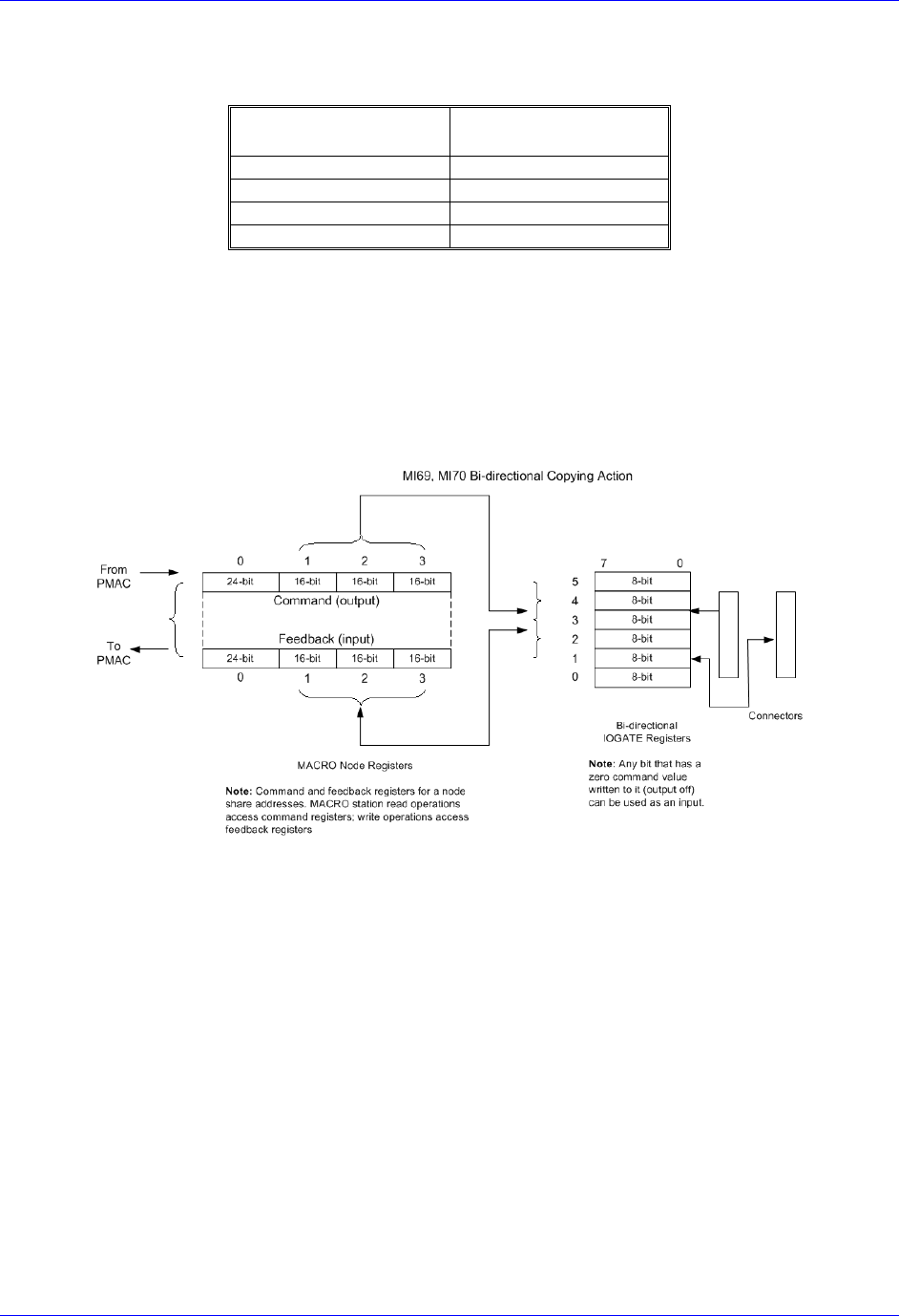
MI69 and MI70 can copy data between one, two, or three 48-bit IOGATE ICs at the same base address
and one, two, or three sets of three 16-bit registers in MACRO I/O nodes. The first IOGATE must be in
the low byte of the address, the second (if used) must be in the middle byte of this address, and the third
(if used) must be in the high byte. The first IOGATE is matched to the three 16-bit registers in the
MACRO I/O node whose address is specified, the second to these registers in the next MACRO I/O node,
and third to the registers in the following MACRO I/O node.
MI71 can copy data between one, two, or three 48-bit IOGATE ICs at the same base address and pairs of
24-bit registers in adjacent MACRO I/O nodes. The first IOGATE must be in the low byte of the address,
the second (if used) must be in the middle byte of this address, and the third (if used) must be in the high
byte.
The first IOGATE is matched to the 24-bit register in the MACRO I/O node whose address is specified
and the 24-bit register in the next MACRO I/O node. The second IOGATE (if used) is matched to the 24-
bit registers in the next pair of MACRO I/O nodes. The third (if used) is matched to the 24-bit registers
in the following pair of MACRO I/O nodes.