
User's Manual
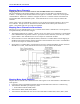
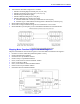
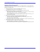

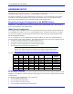
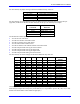

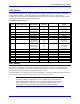
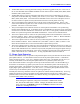
Table Of Contents
- 16-Axis MACRO Slave Station Binding to a MACRO Master
- Mapping Servo Channels to Servo Node
- Mapping Motor Node Registers
- Mapping Motor Function Registers to Node Registers
- Mapping of General Purpose I/O
- UMAC (Pack) Configuration
- I/O Accessory Boards
- Auto Configuration and Identification of UMAC (Pack) Boards
- UMAC (Pack) Interface/Breakout Boards
- MACRO Ring Rules
- I7: Phase Cycle Extension
- I19: Clock Source I-Variable Number
- Turbo PMAC2 Ultralite: I6800 and I6801
- UMAC Turbo
- Notes on Servo Clock
- I6840: MACRO IC 0 Master Configuration
- I6890/I6940/I6990: MACRO IC 1/2/3 Master Configuration
- I6841/I6891/I6941/I6991: MACRO IC 0/1/2/3 Node Activation Control
- I70/I72/I74/I76: MACRO IC 0/1/2/3 Node Auxiliary Function Enable
- I71/I73/I75/I77: MACRO IC 0/1/2/3 Node Protocol Type Control
- I78: MACRO Master/Slave Auxiliary Communications Timeout
- I79: MACRO Master/Master Auxiliary Communications Timeout
- I80, I81, I82: MACRO Ring Check Period and Limits
- Ixx01: Commutation Enable
- Ixx02: Command Output Address
- Ixx03, Ixx04: Feedback Address
- Ixx10, Ixx95: Absolute Position Address and Format
- Ixx25, Ixx24: Flag Address and Mode
- Ixx70, Ixx71: Commutation Cycle Size
- Ixx75: Absolute Phase Position Offset
- Ixx81, Ixx91: Power-On Phase Position Address and Mode
- Ixx82: Current Loop Feedback Address
- Ixx83: Commutation Feedback Address
- Ring Update Frequency
- Station Servo Clock Frequency
- MACRO IC 0
- MACRO IC 1
- MACRO IC 0
- MACRO IC 1
- Channels 1-4 (First 4-Axis Board)
- Channels 5-8 (Second 4-Axis Board)
- On Board Auxiliary Channels (Handwheel/Pulse and Direction)
- Incremental Digital Encoder Feedback
- Analog Encoder Feedback
- Resolver Feedback
- MLDT Feedback
- 12-Bit A/D Converter Feedback
- 14E Parallel Feedback
- MI17 Amplifier Fault Disable Control
- MI18 Amplifier Fault Polarity Control
- MI10x Position Feedback Address
- MI11x Power-On Position Feedback Address
- MI16x Power-On MLDT Excitation Value
- MI975 I/O Node Enable
- MI19 I/O Transfer Period
- Bi-Directional I/O Transfer Control
- Uni-Directional I/O Transfer Control
- Setting the Trigger Condition
- Using for Homing
- Using in User Program
- Setting up for a Single Pulse Output
- Setting up for Multiple Pulse Outputs
- How to Enable and Disable MACRO ASCII Communication Mode
- The Ring Order Method
- Example: Read Using MM-Variables – Actual Encoder
- Example: Read DAC Output from Servo IC Card
- Example: Monitor Up/Down Counter from Servo IC Card
- Example: Write to DACnB on Servo IC Card
- Example: Read Using MI198 and MI199 – Direct Hal
- Example: Read Using MI198 and MI199 – Actual DAC

16-Axis MACRO CPU User Manual
8 Hardware Setup
For these boards, the jumper settings and the board addresses they select are:
Address Jumper On Board Base Address
E1 (CS10) $8800, $9800, $A800,$B800
E2 (CS12) $8840, $9840, $A840,$B840
E3 (CS14) $8880, $9880, $A880,$B880
E4 (CS16) $88C0, $98C0, $A8C0,$B8C0
For these boards, up to three boards can share an address because each board only occupies one byte
(eight bits) of the 24-bit data bus and each board can be set up as to which byte it occupies:
E6A- H Rows
Connected
Byte Used on
Data Bus
1 and 2 Low (Bits 0 – 7)
2 and 3 Middle (Bits 8 – 15)
3 and 4 Middle (Bits 8 – 15)
4 and 5 High (Bits 16 – 23)
The I/O boards available presently whose addresses are set by DIP-switches are:
• Acc-14E 48-TTL-I/O board
• Acc-28E 2/4-channel 16-bit ADC board
• Acc-36E 16-channel 12-bit ADC board
• Acc-53E SSI encoder interface board
• Acc-59E 8-channel 12-bit ADC/8-channel 12-bit DAC board
• Acc-65E self-protected sourcing 24 in/24 out board
• Acc-66E self-protected sourcing 48 input board
• Acc-67E self-protected sourcing 48 output board
• Acc-68E self-protected sinking 24 in/24 out board
For these boards, the switch settings and the board addresses they select are:
S1-1 S1-2 S1-3 S1-4 S1-5 S1-6 I/O Cards Board Base
Address
ON ON ON ON ON ON 1 $8800-$883F
OFF ON ON ON ON ON 2 $9800-$983F
ON OFF ON ON ON ON 3 $A800-$A83F
OFF OFF ON ON ON ON 4 $B800-$B83F
ON ON OFF ON ON ON 5 $8840-$887F
OFF ON OFF ON ON ON 6 $9840-$987F
ON OFF OFF ON ON ON 7 $A840-$A87F
OFF OFF OFF ON ON ON 8 $B840-$B87F
ON ON ON OFF ON ON 9 $8880-$88BF
OFF ON ON OFF ON ON 10 $9880-$98BF
ON OFF ON OFF ON ON 11 $A880-$A8BF
OFF OFF ON OFF ON ON 12 $B880-$B8BF
ON ON OFF OFF ON ON 13 $88C0-$88C7
OFF ON OFF OFF ON ON 14 $98C0-$98C7
ON OFF OFF OFF ON ON 15 $A8C0-$A8C7
OFF OFF OFF OFF ON ON 16 $B8C0-$B8C7
Generally, with these boards it is possible to put only one board at any given address. (The Acc-14E
board always occupies the low byte only of the data bus, so it is possible to put Acc-9E, 10E, 11E, or 12E
boards at the same address in the middle or high bytes.)