
User's Manual
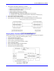
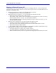

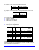

Table Of Contents
- 16-Axis MACRO Slave Station Binding to a MACRO Master
- Mapping Servo Channels to Servo Node
- Mapping Motor Node Registers
- Mapping Motor Function Registers to Node Registers
- Mapping of General Purpose I/O
- UMAC (Pack) Configuration
- I/O Accessory Boards
- Auto Configuration and Identification of UMAC (Pack) Boards
- UMAC (Pack) Interface/Breakout Boards
- MACRO Ring Rules
- I7: Phase Cycle Extension
- I19: Clock Source I-Variable Number
- Turbo PMAC2 Ultralite: I6800 and I6801
- UMAC Turbo
- Notes on Servo Clock
- I6840: MACRO IC 0 Master Configuration
- I6890/I6940/I6990: MACRO IC 1/2/3 Master Configuration
- I6841/I6891/I6941/I6991: MACRO IC 0/1/2/3 Node Activation Control
- I70/I72/I74/I76: MACRO IC 0/1/2/3 Node Auxiliary Function Enable
- I71/I73/I75/I77: MACRO IC 0/1/2/3 Node Protocol Type Control
- I78: MACRO Master/Slave Auxiliary Communications Timeout
- I79: MACRO Master/Master Auxiliary Communications Timeout
- I80, I81, I82: MACRO Ring Check Period and Limits
- Ixx01: Commutation Enable
- Ixx02: Command Output Address
- Ixx03, Ixx04: Feedback Address
- Ixx10, Ixx95: Absolute Position Address and Format
- Ixx25, Ixx24: Flag Address and Mode
- Ixx70, Ixx71: Commutation Cycle Size
- Ixx75: Absolute Phase Position Offset
- Ixx81, Ixx91: Power-On Phase Position Address and Mode
- Ixx82: Current Loop Feedback Address
- Ixx83: Commutation Feedback Address
- Ring Update Frequency
- Station Servo Clock Frequency
- MACRO IC 0
- MACRO IC 1
- MACRO IC 0
- MACRO IC 1
- Channels 1-4 (First 4-Axis Board)
- Channels 5-8 (Second 4-Axis Board)
- On Board Auxiliary Channels (Handwheel/Pulse and Direction)
- Incremental Digital Encoder Feedback
- Analog Encoder Feedback
- Resolver Feedback
- MLDT Feedback
- 12-Bit A/D Converter Feedback
- 14E Parallel Feedback
- MI17 Amplifier Fault Disable Control
- MI18 Amplifier Fault Polarity Control
- MI10x Position Feedback Address
- MI11x Power-On Position Feedback Address
- MI16x Power-On MLDT Excitation Value
- MI975 I/O Node Enable
- MI19 I/O Transfer Period
- Bi-Directional I/O Transfer Control
- Uni-Directional I/O Transfer Control
- Setting the Trigger Condition
- Using for Homing
- Using in User Program
- Setting up for a Single Pulse Output
- Setting up for Multiple Pulse Outputs
- How to Enable and Disable MACRO ASCII Communication Mode
- The Ring Order Method
- Example: Read Using MM-Variables – Actual Encoder
- Example: Read DAC Output from Servo IC Card
- Example: Monitor Up/Down Counter from Servo IC Card
- Example: Write to DACnB on Servo IC Card
- Example: Read Using MI198 and MI199 – Direct Hal
- Example: Read Using MI198 and MI199 – Actual DAC

16-Axis MACRO CPU User Manual
Hardware Setup 9
Auto Configuration and Identification of UMAC (Pack) Boards
The 16-Axis MACRO CPU identifies all the UMAC Servo IC type boards in the Ubus backplane
automatically. From this list, it then attaches them to the two MACRO ICs. Each MACRO IC will
support and configure eight servo channels and six encoder feedback channels.
BITn Fault/Status Description (MI4)
15 Detected Ubus Encoder IC #7 Attached to MACRO IC 0 and 1 (2 channels each)
16 Detected Ubus Encoder #6 Attached to MACRO IC 1 (4 encoder channels)
17 Detected Ubus Encoder #5 Attached to MACRO IC 0 (4 encoder channels)
18 Detected Ubus Servo IC #4 Attached to MACRO IC 1 (4 full servo channels)
19 Detected Ubus Servo IC #3 Attached to MACRO IC 1 (4 full servo channels)
20 Detected Ubus Servo IC #2 Attached to MACRO IC 0 (4 full servo channels)
21 Detected Ubus Servo IC #1 Attached to MACRO IC 0 (4 full servo channels)
22 Detected CPU MACRO IC 1 ($C0C0)
23 Detected CPU MACRO IC 0 ($C080)
Wiring into the MACRO Station
The connections detailed in the Hardware Reference manuals establish the first mapping required
between the physical devices and the machine interface channels on the MACRO Station. For the UMAC
pack, the interface circuitry and breakout connectors are on the same rack-mounted boards, so the field
wiring is made directly into these boards.
UMAC (Pack) Interface/Breakout Boards
The UMAC boards available presently that interface to the MACRO CPU board through the UBUS
backplane include:
• Acc-24E2 2/4-channel PWM servo interface/breakout board
• Acc-24E2A 2/4-channel analog servo interface/breakout board
• Acc-24E2S 4-channel stepper/encoder interface/breakout board
• Acc-51E high-resolution encoder-interpolator board
• Acc-9E isolated 48-input board
• Acc-10E isolated 48-output board
• Acc-11E isolated 24 in/24 out board
• Acc-12E isolated 24 in/24 high-power out board
• Acc-14E 48-TTL output board
• Acc-28E 2/4-channel 16-bit ADC board
• Acc-36E 16-channel 12-bit ADC board (V1.115 or newer firmware required)
• Acc-53E SSI encoder interface board
• Acc-59E 8-channel 12-bit ADC/8-channel 12-bit DAC board (V1.115 or newer firmware required)
• Acc-65E self-protected sourcing 24 in/24 out board
• Acc-66E self-protected sourcing 48 input board
• Acc-67E self-protected sourcing 48 output board
• Acc-68E self-protected sinking 24 in/24 out board
All of these boards provide their own breakout connectors, so no additional breakout boards are required
for the field wiring. Consult the manual for each of these accessory boards for detailed pinout
information.