
User's Manual
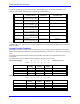

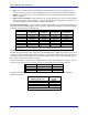
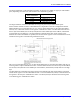
Table Of Contents
- 16-Axis MACRO Slave Station Binding to a MACRO Master
- Mapping Servo Channels to Servo Node
- Mapping Motor Node Registers
- Mapping Motor Function Registers to Node Registers
- Mapping of General Purpose I/O
- UMAC (Pack) Configuration
- I/O Accessory Boards
- Auto Configuration and Identification of UMAC (Pack) Boards
- UMAC (Pack) Interface/Breakout Boards
- MACRO Ring Rules
- I7: Phase Cycle Extension
- I19: Clock Source I-Variable Number
- Turbo PMAC2 Ultralite: I6800 and I6801
- UMAC Turbo
- Notes on Servo Clock
- I6840: MACRO IC 0 Master Configuration
- I6890/I6940/I6990: MACRO IC 1/2/3 Master Configuration
- I6841/I6891/I6941/I6991: MACRO IC 0/1/2/3 Node Activation Control
- I70/I72/I74/I76: MACRO IC 0/1/2/3 Node Auxiliary Function Enable
- I71/I73/I75/I77: MACRO IC 0/1/2/3 Node Protocol Type Control
- I78: MACRO Master/Slave Auxiliary Communications Timeout
- I79: MACRO Master/Master Auxiliary Communications Timeout
- I80, I81, I82: MACRO Ring Check Period and Limits
- Ixx01: Commutation Enable
- Ixx02: Command Output Address
- Ixx03, Ixx04: Feedback Address
- Ixx10, Ixx95: Absolute Position Address and Format
- Ixx25, Ixx24: Flag Address and Mode
- Ixx70, Ixx71: Commutation Cycle Size
- Ixx75: Absolute Phase Position Offset
- Ixx81, Ixx91: Power-On Phase Position Address and Mode
- Ixx82: Current Loop Feedback Address
- Ixx83: Commutation Feedback Address
- Ring Update Frequency
- Station Servo Clock Frequency
- MACRO IC 0
- MACRO IC 1
- MACRO IC 0
- MACRO IC 1
- Channels 1-4 (First 4-Axis Board)
- Channels 5-8 (Second 4-Axis Board)
- On Board Auxiliary Channels (Handwheel/Pulse and Direction)
- Incremental Digital Encoder Feedback
- Analog Encoder Feedback
- Resolver Feedback
- MLDT Feedback
- 12-Bit A/D Converter Feedback
- 14E Parallel Feedback
- MI17 Amplifier Fault Disable Control
- MI18 Amplifier Fault Polarity Control
- MI10x Position Feedback Address
- MI11x Power-On Position Feedback Address
- MI16x Power-On MLDT Excitation Value
- MI975 I/O Node Enable
- MI19 I/O Transfer Period
- Bi-Directional I/O Transfer Control
- Uni-Directional I/O Transfer Control
- Setting the Trigger Condition
- Using for Homing
- Using in User Program
- Setting up for a Single Pulse Output
- Setting up for Multiple Pulse Outputs
- How to Enable and Disable MACRO ASCII Communication Mode
- The Ring Order Method
- Example: Read Using MM-Variables – Actual Encoder
- Example: Read DAC Output from Servo IC Card
- Example: Monitor Up/Down Counter from Servo IC Card
- Example: Write to DACnB on Servo IC Card
- Example: Read Using MI198 and MI199 – Direct Hal
- Example: Read Using MI198 and MI199 – Actual DAC

16-Axis MACRO CPU User Manual
16-Axis MACRO CPU Software Setup 47
Typically, on the MACRO Station accessories the fault bit is brought in through an AC Opto component,
for which current flowing in either direction creates a logical 0. In the default setup of MI18, this state is
considered an amplifier fault. Note that if nothing is connected to such an amplifier fault input, the
matching bit of MI18 must be set to 0 in order for the Station to consider the channel not to be in a fault
condition.
Bit 23 of Ix25 on a PMAC2 or Bit 23 of Ixx24 on a Turbo PMAC2, for the motor assigned to this node,
which controls the amplifier fault polarity at the controller, must be the same value as the matching bit of
MI18. The Station will pass back the amplifier fault bit to the PMAC2 in the same polarity it receives it
and any MACRO fault passed back using this same bit will be of the same polarity.
Servo Address Variable Setup
There are a few MI-Variables for each motor node. Because the motor nodes are not consecutively
numbered (0, 1, 4, 5, 8, 9, 12, 13), these variables specify the node not by its number but by its order (e.g.
Node 0 is the first motor node). The following table provides an easy reference:
Node Number n
0 1 4 5 8 9 12 (C) 13 (D)
Node Order x
1 2 3 4 5 6 7 8
The last digit of the MI-Variable number is represented generally by x, where x represents the order of the
motor node – the xth motor node. In most cases, x will also represent the Machine Interface Channel
used on the 16-Axis MACRO CPU, and the Motor number on PMAC.
MI10x Position Feedback Address
After the initial processing of the feedback in the Station’s encoder conversion table, the data is copied to
the feedback register of a motor node. Station MI-Variable MI10x for the xth motor node used contains
the address of the register, usually one in the conversion table, from which the feedback data is copied
into the position feedback register of the node. Because the conversion table occupies registers $0020 to
$003F in the Station, typically the values of the MI10x variables contain address values in this range.
MI11x Power-On Position Feedback Address
If absolute power-on position is desired for either commutation phase referencing or complete position
referencing, MI11x for the xth motor node on the 16-Axis MACRO CPU must be set to a value greater
than zero.
MI16x Power-On MLDT Excitation Value
If a magnetostrictive linear displacement transducer (MLDT) is to receive its excitation pulses from the
16-Axis MACRO CPU, MI16x is used for the xth motor node to set the frequency of the excitation
immediately upon power-up or reset so the absolute power-on position of the sensor can be read. If
MI16x is greater than 0, this value is copied into the C output register for the machine interface channel
corresponding to the xth motor node (as determined by the SW1 setting) as part of the reset function of
the Station. Thereafter, only A and B command values are copied from the MACRO node command
registers to the machine interface channel registers.
The period between output pulses should be slightly longer than the longest delay in receiving the echo
pulse. This delay can be computed by multiplying the length of the MLDT by the speed of sound in the
MLDT, usually about 2.8 mm/µsec (0.11 in/µsec). With the output period decided, MI16x can be
computed according to the formula:
MI16x = 16,777,216 / [Output_Period (µsec) * PFMCLKfreq (MHz)]
For example, to get an output period of 500 µsec (2kHz frequency) with PFMCLK at the default
frequency of 9.83 MHz, MI16x can be computed as:
MI16x = 16,777,216 / (500 * 9.83) = 3413