25 ^1 HARDWARE REFERENCE MANUAL ^2 Brick Motion Controller ^3 Programmable Servo Amplifier ^4 5xx-603869-xUxx ^5 May 2, 2007 Single Source Machine Control Power // Flexibility // Ease of Use 21314 Lassen Street Chatsworth, CA 91311 // Tel. (818) 998-2095 Fax. (818) 998-7807 // www.deltatau.
Copyright Information © 2007 Delta Tau Data Systems, Inc. All rights reserved. This document is furnished for the customers of Delta Tau Data Systems, Inc. Other uses are unauthorized without written permission of Delta Tau Data Systems, Inc. Information contained in this manual may be updated from time-to-time due to product improvements, etc., and may not conform in every respect to former issues. To report errors or inconsistencies, call or email: Delta Tau Data Systems, Inc.
After removing the power source from the equipment, wait at least 10 minutes before touching or disconnecting sections of the equipment that normally carry electrical charges (e.g., capacitors, contacts, screw connections). To be safe, measure the electrical contact points with a meter before touching the equipment. The following text formats are used in this manual to indicate a potential for personal injury or equipment damage.
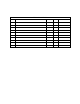
REVISION HISTORY REV. 1 DESCRIPTION MANUAL CREATION DATE CHG APPVD 05/02/07 CP S.
Brick Motion Controller Hardware Reference Manual Table of Contents 125 ................................................................................................................................................................................. I Copyright Information.............................................................................................................................................. ii Operating Conditions .......................................................................
Brick Motion Controller Hardware Reference Manual APPENDIX B.............................................................................................................................................................38 Schematics...............................................................................................................................................................38 X15: Watchdog ..........................................................................................................
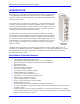
Brick Motion Controller Hardware Reference Manual INTRODUCTION The Brick Motion Controller is a fully scaleable automation controller utilizing the intelligence and capability of its embedded Turbo PMAC2. With the ability to store programs locally and built-in PLC execution, it is programmable for virtually any kind of automation application. This allows for complete machine motion and logic control.
Brick Motion Controller Hardware Reference Manual • • • • • • • • • 2 Primary encoder for each axis with TTL differential/single-ended inputs with A, B quadrature channels and C index channel, 10 MHz cycle rate, and digital Hall-effect inputs Five flags per axis using DB-25: HOME, PLIM, MLIM and USER inputs; EQU compare Optional analog inputs and outputs, ± 5VDC Optional two PWM outputs.
Brick Motion Controller Hardware Reference Manual SPECIFICATIONS Part Number Brick Controller Model Number Definition Axis 1-4 Output Options F: Filtered-PWM analog output on Channels1-4, 12-bit resolution (default) D: Dual true-DAC analog outputs on Channels1-4, 18-bit resolution CPU Options - Turbo PMAC 2 Processor Digital I/O Option C0 : 80Mhz, 8Kx24 Internal, 256Kx24SRAM, 1MB Flash (Default) F3: 240Mhz, 192Kx24 Internal, 1Mx24SRAM, 4MB Flash 0: Digital I/O 16 inputs and 8 outputs, 0.
Brick Motion Controller Hardware Reference Manual Analog I/O Options • • Two 16-bit analog inputs Four 16-bit analog inputs Communication Options • • • • • • • DPRAM option, size 32K x 16-bit wide (required for use with NC software) ModBus Ethernet Communication Protocol (Software) option DPRAM and Modbus options combined RS232 port on 9-pin D-sub connector DPRAM & RS232 options combined Modbus & DPRAM options combined Modbus, DPRAM & RS232 options combined MACRO and Special Feedback Options Number and
Brick Motion Controller Hardware Reference Manual RECEIVING AND UNPACKING Delta Tau products are thoroughly tested at the factory and carefully packaged for shipment. When the Brick Motion Controller is received, there are several steps that should be performed immediately: 1. Observe the condition of the shipping container and report any damage immediately to the commercial carrier that delivered the drive. 2. Remove the control from the shipping container and remove all packing materials.
Brick Motion Controller Hardware Reference Manual 6 Specifications
Brick Motion Controller Hardware Reference Manual SYSTEM WIRING WARNING: Installation of electrical control equipment is subject to many regulations including national, state, local, and industry guidelines and rules. General recommendations can be stated but it is important that the installation be carried out in accordance with all regulations pertaining to the installation. Noise Problems When problems do occur often it points to electrical noise as the source of the problem.
Brick Motion Controller Hardware Reference Manual Connectors X1-X8: Encoder Input (1 to 8) The main encoder input channels for the Brick Motion Controller support only differential quadrature feedback. 5V supply to power the encoder is provided. • 4-axis drives with no Option 01 or Option 02 have only X1 to X4, for a total of four encoders • Option 01 adds two extra S. encoders: X5 and X6, for a total of six encoders • Option 02 adds two more S.
Brick Motion Controller Hardware Reference Manual X9-10: Analog I/O Ch5 (X9) and Ch6 (X10), (Optional) X9/10 (Female DB-9 Connector) Pin # Symbol Function Notes 1 AGND Common 2 ADC5/6+ Input 16-bit Analog Input, channel 5/6+ * 3 4 5 6 ADC5/6Input 16-bit Analog Input, channel 5/6+ * 7 8 9 For spacing specifications between the DB- connectors, see Appendix A of this manual.
Brick Motion Controller Hardware Reference Manual X13: USB 2.0 Connector This connector is used in conjunction with USB A-B cable, which can be purchased from any local computer store and is provided when Option 1A is ordered. The A connector is connected to a PC or Hub device; the B connector plugs into the J9-USB port. X14: RJ45, Ethernet Connector This connector is used for Ethernet communications from the Geo PMAC Drive to a PC.
Brick Motion Controller Hardware Reference Manual TB1: Power Connector The TB1 connector at the bottom panel allows the user to supply 24V DC power for the Brick Controller. 1 Watchdog (TB1) (Phoenix 3-pin Terminal Block) Pin # 1 2 3 Symbol +24VDC Chassis GND +24V return Function Input Input Input 2 3 TB -5: 016-P L0F05-38P Notes S1: Re-Initialization on Reset Control Hold switch in during power cycle for PMAC re-initialization.
Brick Motion Controller Hardware Reference Manual J4 Limit Inputs (1-4 Axis) The Brick Motion Controller limit and flag circuits give the flexibility to wire in standard 12V to 24V limits and flags or wire in 5V level limits and flags on a channel basis. The default is set for the standard 12V to 24V inputs, but if the resistor pack is added to the circuit, the card can read 5V inputs.
Brick Motion Controller Hardware Reference Manual J5 Limit Inputs (5-8 Axis) The Brick Motion Controller limit and flag circuits give the flexibility to wire in standard 12V to 24V limits and flags or wire in 5V level limits and flags on a channel basis. The default is set for the standard 12V to 24V inputs, but if the resistor pack is added to the circuit, the card can read 5V inputs. Note: J5 comes only with the 8-axis configuration.
Brick Motion Controller Hardware Reference Manual A sample of the positive limit circuit is shown below. The 4.7K resistor packs used will allow 12-24V flag inputs. If 0-5V flags are used, then a 1KΩ resistor pack (RP) can be placed in: Flags 1-4: RP39 (channel 1), RP43 (channel 2), RP 47 (channel 3), RP51 (channel 4) Flags 5-8: RP89 (channel 5), RP93 (channel 6), RP 97 (channel 7), and RP 101 (channel 8).
Brick Motion Controller Hardware Reference Manual AMP1-AMP8: Amplifier connections (1 to 8) AMP1-AMP8 Amplifier connections (1-8) (Female DB-15 Connector) 8 7 15 6 14 5 13 4 12 3 11 2 10 Pin # Symbol Function Notes 1 DACnA+ Output DAC A output channel n + 2 DACnB+ Output DAC B output channel n + 3 AE_NCn+ Output Amplifier Enable Relay Normally Open channel n + 4 AE_NOn+ Output Amplifier Enable Relay Normally Closed channel n 5 AFAULTn- Input Amplifier Fault channel n - 6 N.
Brick Motion Controller Hardware Reference Manual Amplifier Fault / Amplifier Enable diagrams 16 System Wiring
Brick Motion Controller Hardware Reference Manual J6: General Purpose I/O J6 General Purpose I/O (Female DB-37 Connector) 19 18 37 17 36 Pin # Symbol Function 1 2 3 4 5 6 7 8 9 10 11 12 13 14 15 16 17 18 19 20 21 22 23 24 25 26 27 28 29 30 31 32 33 34 35 36 37 GPIN01 GPIN03 GPIN05 GPIN07 GPIN09 GPIN11 GPIN13 GPIN15 IN_COM 01-08 N.
Brick Motion Controller Hardware Reference Manual Suggested M-Variable Addressing for the General Purpose I/O (J6) Notes 18 12 13 14 15 16 17 18 19 30 31 32 33 34 35 36 37 Sinking Address M0-> Y:$78800,0,1 Input 1 Data Line, J6 Pin 1 M1-> Y:$78800,1,1 Input 2 Data Line, J6 Pin 20 M2-> Y:$78800,2,1 Input 3 Data Line, J6 Pin 2 M3-> Y:$78800,3,1 Input 4 Data Line, J6 Pin 21 M4-> Y:$78800,4,1 Input 5 Data Line, J6 Pin 3 M5-> Y:$78800,5,1 Input 6 Data Line, J6 Pin 22 M6-> Y:$78800,6,1 Input 7 Data Line, J6
Brick Motion Controller Hardware Reference Manual J7: Extra General Purpose I/O (Optional) J7 General Purpose I/O (Female DB-37 Connector) Pin # Symbol 19 18 37 17 36 Function 16 35 15 34 14 33 13 32 12 31 10 11 30 29 9 28 8 27 7 26 6 25 5 24 4 23 3 22 2 21 1 General purpose I/O is available on the Brick Motion Controller. All I/O is electrically isolated from the drive. Inputs can be configured for sinking or sourcing applications. All Inputs are 12-24VDC.
Brick Motion Controller Hardware Reference Manual Suggested M-Variable Addressing for the optional General Purpose I/O (J7) Notes 20 12 13 14 15 16 17 18 19 30 31 32 33 34 35 36 37 Sinking Address M40-> Y:$78803,0,1 Input 17 Data Line, J7 Pin 1 M41-> Y:$78803,1,1 Input 18 Data Line, J7 Pin 20 M42-> Y:$78803,2,1 Input 19 Data Line, J7 Pin 2 M43-> Y:$78803,3,1 Input 20 Data Line, J7 Pin 21 M44-> Y:$78803,4,1 Input 21 Data Line, J7 Pin 3 M45-> Y:$78803,5,1 Input 22 Data Line, J7 Pin 22 M46-> Y:$78803,6,1
Brick Motion Controller Hardware Reference Manual J8: Extra General Purpose I/O (Optional) J8 General Purpose I/O (Female DB-37 Connector) 19 18 37 17 36 Pin # Symbol Function 1 2 3 4 5 6 7 8 9 10 11 12 13 14 15 16 17 18 19 20 21 22 23 24 25 26 27 28 29 30 31 32 33 34 35 36 37 GPIN33 GPIN35 GPIN37 GPIN39 GPIN41 GPIN43 GPIN45 GPIN47 IN_COM 33-40 N.
Brick Motion Controller Hardware Reference Manual Suggested M-Variable Addressing for the General Purpose I/O (J8) Notes 22 12 13 14 15 16 17 18 19 30 31 32 33 34 35 36 37 Sinking Address M64-> Y:$78A00,0,1 Input 33 Data Line, J6 Pin 1 M65-> Y:$78A00,1,1 Input 34 Data Line, J6 Pin 20 M66-> Y:$78A00,2,1 Input 35 Data Line, J6 Pin 2 M67-> Y:$78A00,3,1 Input 36 Data Line, J6 Pin 21 M68-> Y:$78A00,4,1 Input 37 Data Line, J6 Pin 3 M69-> Y:$78A00,5,1 Input 38 Data Line, J6 Pin 22 M70-> Y:$78A00,6,1 Input 39
Brick Motion Controller Hardware Reference Manual Sample J6/J7, I/O Wiring Diagrams 20 2 21 3 4 5 6 22 23 24 25 7 8 26 27 9 28 10 29 11 12 30 13 31 14 32 15 33 34 18 36 19 37 4 5 6 7 8 21 22 23 24 25 26 9 27 10 28 11 8 Output 02 GPO3- Output 03 GPO4- Output 04 Output 05 GPO6- GPIN01 GPIN02 GPIN03 GPIN04 GPIN05 GPIN06 GPIN07 GPIN08 GPIN09 GPIN10 GPIN11 GPIN12 GPIN13 GPIN14 GPIN15 GPIN16 IN_COM_01-08 IN_COM_09-16 29 24 26 9 27 10 28 Output 08 Output 01 13 31
Brick Motion Controller Hardware Reference Manual Setting up Quadrature Encoders Digital quadrature encoders are the most common position sensors used with Geo Drives. Interface circuitry for these encoders comes standard on board-level Turbo PMAC controllers, UMAC axisinterface boards, Geo drives, and QMAC control boxes.
Brick Motion Controller Hardware Reference Manual Encoder Loss Setup The Brick Motion Controller has encoder-loss detection circuitry for each encoder input. Designed for use with encoders with differential line-driver outputs, the circuitry monitors each input pair with an exclusive-or (XOR) gate. If the encoder is working properly and connected to the Brick Motion Controller, the two inputs of the pair should be in opposite logical states – one high and one low – yielding a true output from the XOR gate.
Brick Motion Controller Hardware Reference Manual For more details about Encoder Loss look into the Turbo USERs Manual chapter: Making Your Application Safe. Setting up the Analog Inputs (optional) The Brick Motion Controller can be ordered with two or four 16-bit hi-resolution analog to digital converters. The Brick Motion Controller uses the Burr Brown ADS8361.
Brick Motion Controller Hardware Reference Manual etc.), then writing values to the M-variable. The analog outputs are intended to drive high-impedance inputs with no significant current draw. The 220Ω output resistors will keep the current draw lower than 50 mA in all cases and prevent damage to the output circuitry, but any current draw above 10 mA can result in noticeable signal distortion.
Brick Motion Controller Hardware Reference Manual hardware clock signals are SCLK (encoder sample clock), PFM_CLK (pulse frequency modulator clock), DAC_CLK (digital-to-analog converter clock), and ADC_CLK (analog-to-digital converter clock). Parameters to Set Up Per-Channel Hardware Signals I70n6 is the output mode; “n” is the output channel number (i.e. for channel 1 the variable to set would be I7016, I7026 for channel 2 etc.). On Pmac1 there is only one output and one output mode, DAC output.
Brick Motion Controller Hardware Reference Manual Setting up for Pulse and Direction Output The following section shows how to quickly setup the key variables for a stepper motor (PFM) system. The step and direction outputs are RS422 compatible and are capable of being connected in either differential mode or single ended configurations for 5V input drivers. Below are two examples for wiring the Brick Motion Controller to the stepper Amplifier.
Brick Motion Controller Hardware Reference Manual I7m04: PFM Pulse Width Control The pulse width is specified in PFM clock cycles and has a range of 1 to 255 cycles. The default value is 15. Since the default value of PFM clock is actually set to 9.8304 MHz, the default output pulse width will be 15/9,830400 = 1.5258 µS. Note that when the PFM clock values are changed, the PFM pulse width values must be evaluated for proper stepper drive operation.
Brick Motion Controller Hardware Reference Manual Ixx30: Motor xx Proportional Gain To create a closed loop position response with a natural frequency of approximately 25 Hz and a damping ratio of 1, use the following calculation: Ixx30 = 660 ,000 Ixx08 * PFMCLK ( MHz ) Example: PFMCLK is set to default of 9.83 MHz, and Ixx08 is set to default of 96. Ixx30 = 660,000 / (96 * 9.83) = 700.
Brick Motion Controller Hardware Reference Manual Example: User wants channels 5 to 8 to be used with stepper motors. First the user needs to wire the Stepper drive, and so as to enable the Stepper output pin 8 needs to be shorted to pin 4 (+5V) for X5 to X8. Assume for this example that all the stepper motors that will be used do not have encoders for feedback.
Brick Motion Controller Hardware Reference Manual Watchdog Timer Brick Motion Controller has an on-board watchdog timer. This subsystem provides a fail-safe shutdown to guard against software and hardware malfunction. To keep it from tripping the hardware circuit for the watchdog timer requires that two basic conditions be met. First, it must see a DC voltage greater than approximately 4.75V.
Brick Motion Controller Hardware Reference Manual • Disconnect any accessories and cables other than the logic power and repeat to see if they are causing the problem • Check for adequate 24V power supply levels (check at the Brick Motion Controller connector side, not at the supply) • Inspect for hardware damage 4. If the watchdog insists after all the above, you should contact DeltaTau Inc. to get an RMA number, and ship the drive for repairs.
Brick Motion Controller User Manual – Preliminary Documentation APPENDIX A DB- Connector Spacing Specifications X1-8: DB-15 Connectors for encoder feedback 3.115±.05 1.541±.015 8 7 15 6 14 5 13 4 12 3 11 2 10 1 8 9 7 15 6 14 5 13 4 12 3 11 2 10 1 9 X9-12: DB-9 Connectors for Analog I/O 2.45±.05 1.213+.015 5 4 9 3 8 2 7 1 5 6 4 9 3 8 2 7 1 6 Screw Lock Size for all DB-connectors .18 7 #4-40 FEMALE SCREWLOCK QTY 2 per connector Steel, Zinc Plated Appendix A .
Brick Motion Controller Hardware Reference Manual Type of Cable for Encoder Wiring Low capacitance shielded twisted pair cable is ideal for wiring differential encoders. The better the shield wires, the better the noise immunity to the external equipment wiring. Wiring practice for shielded cables is not an exact science. Different applications will present different sources of noise, and experimentation may be required to achieve the desired results.
Brick Motion Controller User Manual – Preliminary Documentation Note: If noise is a problem in the application, careful attention must be given to the method of grounding that is used in the system. Amplifier and motor grounding can play a significant role in how noise is generated in a machine. Noise may be reduced in a motor-based system by the use of inductors placed between the motor and the amplifier.
Brick Motion Controller Hardware Reference Manual APPENDIX B Schematics X15: Watchdog DGND_PLANE BWDO 3 4 5 3 2 4 D18 MMBD301LT1 (SOT23) 9 1 12 TB2 1 2 3 5 K5 NC7SZ08M5 (SOT23-5) 1 1 WDO 3 WDO U29 (JWDO) COM N.C. N.O. TERMBLK 3 (.150 PITCH) 10 8 FBR12ND05 DGND_PLANE GND J6 and J7: General Purpose I/O Inputs MMBZ33VALT1 .1uf C243 .1uf U70 ACI1A ACI1B ACI2A ACI2B ACI3A ACI3B ACI4A ACI4B C1 E1 C2 E2 C3 E3 C4 E4 7 5 3 1 2 D57 1 2 D56 1 D55 D58 2 4 6 8 RP160 2.
Brick Motion Controller User Manual – Preliminary Documentation Outputs D71 Opto Gnd Plane 2 2.2K D74 D75 D76 2 2 2 2 2 D73 D77 D78 1 1 1 1 1 1 1 1 GPO1+ RUE090 Raychem 30R090 Littelfuse GPO1-- 3 R80 Q5 NZT560A (SOT-223) D72 MBRS140T3 MBRS140T3 MBRS140T3 MBRS140T3 MBRS140T3 MBRS140T3 MBRS140T3 MBRS140T3 F1 1 2 2 2 COM_COL 5 6 7 8 ANO2 CAT2 C2 E2 ANO3 CAT3 C3 E3 ANO4 CAT4 C4 E4 16 15 14 13 1 R81 2.2K GPO2-F3 12 11 10 9 1 R82 2.
Brick Motion Controller Hardware Reference Manual J4: Limit Inputs for Axis 1-4 16 15 14 13 12 11 10 9 U39 C1 E1 AC1 AC1 C2 E2 AC2 AC2 C3 E3 AC3 AC3 C4 E4 AC4 AC4 1 2 1 3 5 7 3 4 5 6 7 8 PS2705-4 16 15 14 13 12 11 10 9 U40 C1 E1 AC1 AC1 C2 E2 AC2 AC2 C3 E3 AC3 AC3 C4 E4 AC4 AC4 C160 C162 .1 .1 C161 C163 .1 .1 1 2 5 6 7 8 PS2705-4 16 15 14 13 12 11 10 9 U41 C1 E1 AC1 AC1 C2 E2 AC2 AC2 C3 E3 AC3 AC3 C4 E4 AC4 AC4 C164 C166 .1 .1 C165 C167 .1 .
Brick Motion Controller User Manual – Preliminary Documentation J5: Limit Inputs for Axis 5-8 16 15 14 13 12 11 10 9 U59 C1 E1 AC1 AC1 C2 E2 AC2 AC2 C3 E3 AC3 AC3 C4 E4 AC4 AC4 1 2 1 3 5 7 3 4 5 6 7 8 PS2705-4 16 15 14 13 12 11 10 9 U60 C1 E1 AC1 AC1 C2 E2 AC2 AC2 C3 E3 AC3 AC3 C4 E4 AC4 AC4 C200 C202 .1 .1 C201 C203 .1 .1 1 2 5 6 7 8 PS2705-4 16 15 14 13 12 11 10 9 U61 C1 E1 AC1 AC1 C2 E2 AC2 AC2 C3 E3 AC3 AC3 C4 E4 AC4 AC4 C204 C206 .1 .1 C205 C207 .1 .
Brick Motion Controller Hardware Reference Manual Dimensional Layout and Connector location 42 Appendix C