
User manual


Brick Controller User Manual
Drive-Motor Setup 151
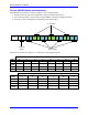
Pulse and Direction Output (PFM)
The Pulse and direction (Pulse Frequency Modulation) output pins are located on the encoder (X1-X8)
connectors. The stepper drive specifications dictate the choice of the maximum PFM clock frequency, and
pulse width.
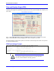
DT Calculator Forum Link
Step 1: Choose Max PFM clock by changing the PFM clock divider. Click on calculate to see results.
Step 2: Choose PFM Pulse width by changing I7m04. Click on calculate to see results.
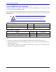
The output frequency control Ixx69 specifies the maximum command output value which corresponds to
the maximum PFM Frequency.
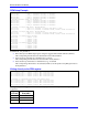
PFM Clock Settings Example
Take a desired PFM clock frequency of 0-20 KHz, and a pulse width of ~20 μsec:
// Channels 1-4 PFM Clock Settings
I7003=2290 ; Servo IC 0 PFM Clock divider equal to 6
I7004=13 ; Servo IC 0 PFM Pulse Width Control equal to 13
I169,4,100=2427 ; Channels 1-4 Output Command Limit
// Channels 5-8 PFM Clock Settings
I7103=2290 ; Servo IC 1 PFM Clock divider equal to 6
I7104=13 ; Servo IC 1 PFM Pulse Width Control equal to 13
I569,4,100=2427 ; Output Command Limit
Note
The following example assumes that there is no encoder attached to
the motor, and the feedback is internally generated.