
User manual


Brick Controller User Manual
PinOuts and Software Setup 55
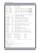
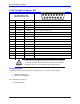
X1-X8: Encoder Feedback, SSI
X1-X8: D-sub DA-15F
Mating: D-sub DA-15M
2
3
4
5
6
7
8
9
10
11
12
13
14
15
1
Pin #
Symbol
Function
Notes
1
2
3
4
EncPwr
Output
Encoder Power 5 Volts only
5
Data-
Input
Data- packet
6
Clock-
Output
Serial Encoder Clock-
7
8
9
10
11
12
GND
Common
Common Ground
13
Clock+
Output
Serial Encoder Clock+
14
Data+
Input
Data+ Packet
15
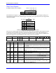
Note
Some SSI devices require 24V power which has to be brought in
externally. Pins #4, and #12 are unused in this case, leave floating.
Hardware capture is not available with Serial Data encoders
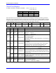
Configuring SSI
Configuring the SSI protocol requires the programming of two essential control registers:
Global Control Registers
Channel Control Registers
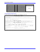
The resulting data is found in:
SSI Data Registers