
User manual


Brick Controller User Manual
PinOuts and Software Setup 60
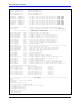
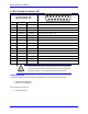
Field
Value
Notes
Channel Control Word
Parity Type
=0
Hex 0x00
$001419
Trigger Mode
=0
Continuous trigger (typical)
Trigger Enable
=1
Enable
Gray / Binary
=0
Binary
Data Ready / Senc Mode
=1
Enable serial driver
Protocol Bits
=25
Hex 0x19
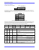
Control Registers Power-On PLC
The global and channel control words have to be executed once on power-up:
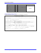
//=========================== NOTES ABOUT THIS PLC EXAMPLE ================================//
// This PLC example utilizes: - M5990 through M5991
// - Coordinate system 1 Timer 1
// Make sure that current and/or future configurations do not create conflicts with
// these parameters.
//=========================================================================================//
M5990..5991->* ; Self-referenced M-Variables
M5990..5991=0 ; Reset at download
//========================= GLOBAL CONTROL REGISTERS ======================================//
#define SSIGlobalCtrl1_4 M5990 ; Channels 1-4 SSI global control register
SSIGlobalCtrl1_4->X:$78B2F,0,24,U ; Channels 1-4 SSI global control register address
//======================== CHANNEL CONTROL REGISTERS ======================================//
#define Ch1SSICtrl M5991 ; Channel 1 SSI control register
Ch1SSICtrl->X:$78B20,0,24,U ; Channel 1 SSI control register Address
//========= POWER-ON PLC EXAMPLE, GLOBAL & CHANNEL CONTROL REGISTERS ======================//
Open PLC 1 Clear
SSIGlobalCtrl1_4=$630002 ; Trigger at Phase, 1 MHz serial Clock (M=99, N=0)–User Input
Ch1SSICtrl=$001419 ; Channel 1 SSI control register –User Input
I5111=500*8388608/I10 while(I5111>0) endw ; ½ sec delay
Dis plc 1 ; Execute once on power-up or reset
Close
//=========================================================================================//