
User manual

Brick Controller User Manual
PinOuts and Software Setup 67
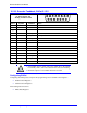
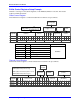
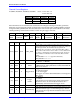
X1-X8: Encoder Feedback, BiSS C/B
X1-X8: D-sub DA-15F
Mating: D-Sub DA-15M
2
3
4
5
6
7
8
9
10
11
12
13
14
15
1
Pin #
Symbol
Function
Notes
1
2
3
4
EncPwr
Output
Encoder Power 5 Volts
5
Data-
Input/Output
Data- packet, SLO-
6
Clock-
Output
Serial Encoder Clock-, MO-
7
8
9
10
11
12
GND
Common
Common Ground
13
Clock+
Output
Serial Encoder Clock+ , MO+
14
Data+
Input/Output
Data+ Packet, SLO+
15
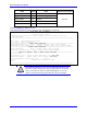
Note
Some BiSS devices require 24V power which has to be brought in
externally. Pins 4, and 12 are unused in this case, leave floating.
Hardware capture is not available with Serial encoders
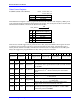
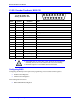
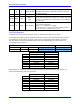
Configuring BiSS
Configuring the BiSS protocol requires the programming of two essential control registers:
Global Control Registers
Channel Control Registers
The resulting data is found in:
BiSS-C/BiSS-B Data Registers