
User manual

Brick Controller User Manual
PinOuts and Software Setup 68
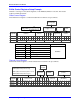
Global Control Registers
X:$78BnF (default value: $18000B) where n=2 for axes 1-4
n=3 for axes 5-8
Global Control Register
Axes 1-4
X:$78B2F
Axes 5-8
X:$78B3F
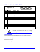
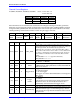
The Global Control register is used to program the serial encoder interface clock frequency SER_Clock
and configure the serial encoder interface trigger clock. SER_Clock is generated from a two-stage divider
clocked at 100 MHz as follows:
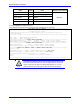
M
N
Clock Frequency
49
0
2.0 MHz
99
0
1.0 MHz
99
1
500.0 KHz
99
2
250.0 KHz
…
…
Default Settings: M=24, N=0 => 4 MHz transfer rates
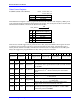
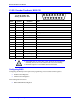
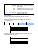
There are two external trigger sources; phase and servo. Bits [9:8] in the Global Control register are used
to select the source and active edge to use as the internal serial encoder trigger. The internal trigger is
used by all four channels to initiate communication with the encoder. To compensate for external system
delays, this trigger has a programmable 4-bit delay setting in 20 μsec increments.
23--16
15--12
11
10
9
8
7
6
5
4
3
2
1
0
M_Divisor
N_Divisor
Trigger Clock
Trigger Edge
Trigger Delay
Protocol Code
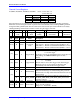
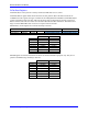
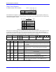
Bit
Type
Default
Name
Description
[23:16]
R/W
0x18
M_Divisor
Intermediate clock frequency for SER_Clock. The
intermediate clock is generated from a (M+1) divider clocked
at 100 MHz.
[15:12]
R/W
0x0
N_Divisor
Final clock frequency for SER_Clock. The final clock is
generated from a
N
2
divider clocked by the intermediate
clock.
[11:10]
R
00
Reserved
Reserved and always reads zero.
[09]
R/W
0
TriggerClock
Trigger clock select: 0= PhaseClock
1= ServoClock
[08]
R/W
0
TriggerEdge
Active clock edge select: 0= rising edge
1= falling edge
[07:04]
R/W
0x0
TriggerDelay
Trigger delay program relative to the active edge of the
trigger clock. Units are in increments of 20 usec.
[03:00]
R
0xB
ProtocolCode
This read-only bit field is used to read the serial encoder interface
protocol supported by the FPGA. A value of $B defines this
protocol as BiSS.