
User manual


Brick Controller User Manual
PinOuts and Software Setup 75
Technique 1 Example
Channel 1 is driving a 25-bit (13-bit Singleturn, 12-bit Multiturn) rotary serial encoder, or a linear scale
with similar protocol resolution (13 bits, 1 micron).
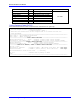
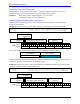
Encoder Conversion Table - for position (Technique 1)
Conversion Type: Parallel pos from Y word with no filtering
Width in Bits: Singleturn/absolute resolution in bits (e.g. 13 bits)
Offset Location of LSB: leave at zero
Normal Shift (5 bits to the left)
Source Address: serial data register A (see table below)
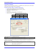
Remember to click on Download Entry for the changes to take effect.
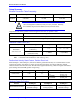
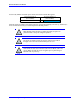
Source Address ( Serial Data Register A)
Channel 1
Y:$78B20
Channel 5
Y:$78B30
Channel 2
Y:$78B24
Channel 6
Y:$78B34
Channel 3
Y:$78B28
Channel 7
Y:$78B38
Channel 4
Y:$78B2C
Channel 8
Y:$78B3C
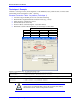
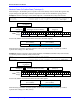
This is a 2-line ECT entry, its equivalent script code:
I8000=$278B20 ; Unfiltered parallel pos of location Y:$78B20
I8001=$00D000 ; Width and Offset. Processed result at $3502
Typically, the position and velocity pointers are set to the processed data address (e.g. $3502):
I100=1 ; Mtr#1 Active. Remember to activate the channel to see feedback
I103=$3502 ; Mtr#1 position loop feedback address
I104=$3502 ; Mtr#1 velocity loop feedback address
Note
At this point, you should be able to move the motor/encoder shaft by
hand and see ‘motor’ counts in the position window.