
User manual


Geo Brick User Manual
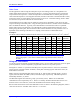
System Wiring 55
For a 6-Axis Geo Brick Drive
On a 6-Axis unit, the analog inputs use channels 7 and 8 of the second gate-array and channels 5 and 6 are
used for the current loop feedback. The strobe word for the current loop feedback is I7106=$3FFFFF,
which will set the strobe word for all the channels on the second gate-array. This then creates a conflict in
reading the analog ADC inputs because it needs a strobe word value of I7106=$1FFFFF for 12-bit option
and 16-bit option. Therefore, to satisfy all of the conditions, we can use M-variable definitions and P-
variables (M and P-Variables are suggested variables) for calculations that will point to the ADC inputs
and setup the strobe word for 12-bit and 16-bit analog option. This can then be put into a PLC program to
run in the background.
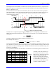
The low-resolution (12-bit) option uses the second gate-array which controls the strobe word for
channels 5 to 8 and is set to I7106=$3FFFFF for the current loop feedback. We can then create an M-
variable (M5000) that will read all the unsigned 24-bits of analog data, which is then copied into a P-
variable (P5000). The copied data in P5000 is shifted one bit to the right, which is set to equal to P5001.
At the same time the first bit of the 24-bits in P5000 is moved to the front and set as P5003. The results of
P5001 and P5003 are added together and then copied into a temporary M-variable location, M5004. The
data in M5004 is 24-bits; therefore we can then set M5005 to point to the upper signed 12-bits of M5004,
which will be the ADC7 12-bit signed analog input. This can be done by using the PLC program below:
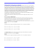
Bipolar
The data received is a signed 12-bit number scaled from -5V to +5V (-2048cts to 2047cts).
M5000->y:$78115,0,24,u
;ch7 M-vars for A-D 24-bit raw data.
M5004->x:$10f0,0,24,u ;ch7 Temp M-vars location 24-bits.
M5005->x:$10f0,12,12,s
;ADC7 12-bit analog input (signed).
M6000->y:$7811d,0,24,u
;ch8 M-vars for A-D unsigned 24-bits.
M6004->x:$10f1,0,24,u ;ch8 Temp M-vars location unsigned 24-bits.
M6005->x:$10f1,12,12,s ;ADC8 12-bit analog input.
i5=2 ;Enables background PLCs.
open plc21 clear
P5000=M5000
;copy values from M5000 to P5000.
P5002=P5000&1
;mask bit 1 (LSB) of P5000.
P5003=P5002*8388608
;move bit 1 of P5000 23 bits forward.
P5001=P5000/2
;move 1 bit to the right of P5000.
M5004=P5001+P5003
;Assemble M-var unsigned 24-bits to temp
;location by adding P5001 and P5003.
P6000=M6000 ;copy values from M6000 to P6000.
P6002=P6000&1 ;mask bit 1 (LSB) of P6000.
P6003=P6002*8388608 ;move bit 1 of P6000 23 bits forward.
P6001=P6000/2 ;move 1 bit to the right of P6000.
M6004=P6001+P6003 ;Assemble M-var unsigned 24-bits to temp
;location by adding P6001 and P6003.
close
After executing this PLC program, the end user can use M5005 and M6005 for ADC7 and ADC8
respectively to read the 12-bit analog input register.
The high-resolution (16-bit) option uses the second gate-array which controls the strobe word for
channels 5 to 8 and is set to I7106=$3FFFFF for the current loop feedback. We can then create an M-
variable (M5000) that will read all the unsigned 24-bits of analog data, which is then copied into a P-
variable (P5000). The copied data in P5000 is shifted one bit to the right, which is set to equal to P5001.