
User manual


Geo Brick User Manual
56 System Wiring
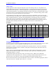
At the same time, the first bit of the 24-bits in P5000 is moved to the front and set as P5003. The results
of P5001 and P5003 are added together and then copied into a temporary M-variable location, M5004.
The data in M5004 is 24-bits; therefore we can then set M5005 to point to the upper signed 16-bits of
M5004, which will be the ADC7 16-bit signed analog input. This can be done by using the PLC program
constructed below:
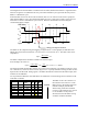
Bipolar
The data received is a signed 16-bit number scaled from -5V to +5V (-32768cts to 32767cts).
M5000->y:$78115,0,24,u ;ch7 M-vars for A-D 24-bit raw data.
M5004->x:$10f1,0,24,u ;ch7 Temp M-vars location 24-bits.
M5005->x:$10f1,8,16,s ;ADC7 16-bit analog input (signed).
M6000->y:$7811d,0,24,u ;ch8 M-vars for A-D unsigned 24-bits.
M6004->x:$10f1,0,24,u ;ch8 Temp M-vars location unsigned 24-bits.
M6005->x:$10f1,8,16,s ;ADC8 16-bit analog input.
i5=2 ;Enables background PLCs.
open plc21 clear
P5000=M5000 ;copy values from M5000 to P5000.
P5002=P5000&1 ;mask bit 1 (LSB) of P5000.
P5003=P5002*8388608 ;move bit 1 of P5000 23 bits forward.
P5001=P5000/2 ;move 1 bit to the right of P5000.
M5004=P5001+P5003 ;Assemble M-var unsigned 24-bits to temp
;location by adding P5001 and P5003.
P6000=M6000 ;copy values from M6000 to P6000.
P6002=P6000&1 ;mask bit 1 (LSB) of P6000.
P6003=P6002*8388608 ;move bit 1 of P6000 23 bits forward.
P6001=P6000/2 ;move 1 bit to the right of P6000.
M6004=P6001+P6003 ;Assemble M-var unsigned 24-bits to temp
;location by adding P6001 and P6003.
close
After executing this PLC program, the end user can use M5005 and M6005 for ADC7 and ADC8
respectively to read the 16-bit analog input registers.