
User manual

Geo Brick Drive User Manual
Pinouts and Software Setup 143
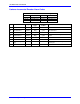
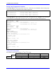
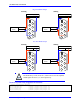
X9-X10: Analog Inputs/Outputs
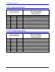
X9-X10: D-Sub DE-9F
Mating: D-Sub DE-9M
2
345
9 8 7 6
1
Pin #
Symbol
Function
Notes
1
AGND
Ground
Analog Ground
2
ADC+
Input
16-bit Analog Input, channel 5/6+
3
DAC+
Output
12-bit filtered PWM analog output, channel 5/6+
4
BR-NC
Output
Brake 5-6 / Relay Normally Closed
5
AMPFLT
Input
Amplifier fault Input 5/6
6
ADC-
Input
16-bit Analog Input, channel 5/6-
7
DAC-
Output
12-bit filtered PWM analog output, channel 5/6-
8
BRCOM
Common
Brake 5-6 / Relay Common
9
BR-NO
Output
Brake 5-6 / Relay Normally Open
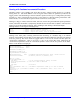
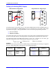
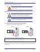
X11-X12: Analog Inputs/Outputs
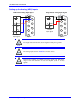
X11-X12: D-Sub DE-9F
Mating: D-Sub DE-9M
2
345
9 8 7 6
1
Pin #
Symbol
Function
Notes
1
AGND
Ground
Analog Ground
2
ADC+
Input
16-bit Analog Input, channel 7/8+
3
DAC+
Output
12-bit filtered PWM analog output, channel 7/8+
4
BR-NC
Output
Brake 3-4 / Relay Normally Closed
5
AMPFLT
Input
Amplifier fault Input 7/8
6
ADC-
Input
16-bit Analog Input, channel 7/8-
7
DAC-
Output
12-bit filtered PWM analog output, channel 7/8-
8
BRCOM
Common
Brake 3-4/ Relay Common
9
BR-NO
Output
Brake 3-4 / Relay Normally Open