
User manual

Geo Brick Drive User Manual
Macro Connectivity 250
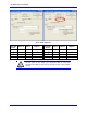
The proposed transfer mechanism establishes the reading of inputs and writing to outputs through bitwise
assignments (single-bit definitions) from the master side.
Outputs: At the master side, the user would write the desired outputs’ state (using the bitwise definitions)
to pre-defined open memory registers which are copied, using a PLC code, into the 24-bit register of
MACRO I/O node 2. At the Slave side, this MACRO I/O node register is copied, using a PLC code, into
the local outputs’ registers which will reflect the user’s outputs’ desired state.
Inputs: At the slave side, the machine’s inputs’ state is copied into first 2 x 16-bit registers of MACRO
I/O node 2. At the master side, these MACRO I/O node registers are copied, using a PLC code, into pre-
defined open memory registers (bitwise definitions) where the user can monitor the machine’s inputs’
state.
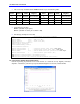
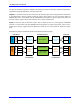
The following diagram summarizes the abovementioned transfer technique:
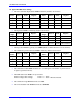
MACRO I/O Node 2
24-bit register
1
st
16-bit register
(upper 16 bits)
2
nd
16-bit register
(upper 16 bits)
Brick SlaveBrick Master
1
st
Byte
2
nd
Byte
OUTPUTS
User Write
1
st
Byte
2
nd
Byte
3
rd
Byte
INPUTS
User Read
4
th
Byte
1
st
Byte
2
nd
Byte
3
rd
Byte
4
th
Byte
Master
PLC Operations
Slave
PLC Operations
Outputs Inputs
Open
Memory
Open Memory
Copy
Outputs to
IO node
Write
Inputs to
Master
Write
outputs to
Slave
Copy
Inputs to
IO node
1
st
Byte
2
nd
Byte