
Installation manual

GEO Direct PWM Amplifiers – Preliminary Documentation
16 Mounting
Motor Line Filtering
Motor filtering may not be necessary for CE compliance of GEO Drives. However, this additional
filtering increases the reliability of the system. Poor non-metallic enclosure surfaces and lengthy,
unbonded (or unshielded) motor cables that couple noise line-to-line (differential) are some of the factors
that may lead to the necessity of motor lead filtering.
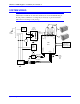
Motor lead noise is either common-mode or differential. The common-mode conducted currents occur
between each motor lead and ground (line-to-neutral). Differential radiated currents exist from one motor
lead to another (line-to-line). The filtering of the lines feeding the motor provides additional attenuation
of noise currents that may enter surrounding cables and equipment I/O ports in close proximity.
Differential mode currents commonly occur with lengthy motor cables. As the cable length increases, so
does its capacitance and ability to couple noise from line-to-line. While every final system is different
and every application of the product causes a slightly different emission profile, it may become necessary
to use differential mode chokes to provide additional noise attenuation to minimize the radiated
emissions. The use of a ferrite core placed at the GEO Drive end on each motor lead attenuates
differential mode noise and lowers frequency (30 to 60 MHz) broadband emissions to within
specifications. Delta Tau Data Systems, Inc., recommends a Fair-Rite P/N 263665702 (or equivalent)
ferrite core.
Common mode currents occur from noise spikes created by the PWM switching frequency of the GEO
Drive. The use of a ferrite or iron-powder core toroid places common mode impedance in the line
between the motor and the GEO Drive. The use of a common mode choke on the motor leads may
increase signal integrity of encoder outputs and associated I/O signals.
I/O Filtering
I/O filtering may be desired, depending on system installation, application, and integration with other
equipment. It may be necessary to place ferrite cores on I/O lines to avoid unwanted signals entering and
disturbing the GEO.
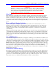
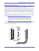
The GEO drives can be mounted three different ways:
1. Traditional 4-hole panel mount, two “U shape”/notches on the bottom and two pear shaped holes on
top. This method keeps the heat sink and fan, if used, inside the mounting enclosure.
This method allows for side-by-side mounting of the single width GEO Amps at 3.4 center-to-center
distance (86 mm). Double width GEO amplifiers mount side by side at 6.7 inch center-to-center
distance (171 mm).
2. A “Through the Panel” mount which requires a hole in the mounting cabinet so that the GEO heat
sink can protrude through the mounting enclosure in order to vent the heat outside the enclosure. A
special “Skirt” with gasket seal is provided for this purpose. Mounting hole pattern is the same as the
traditional mounting for four holes with two additional holes added on the sides.
This method requires clearance for the mounting “skirt.” Single width center-to-center mounting
distance is 4.3 (109mm). Double-width GEO amplifiers have a center-to-center distance of 7.6 inches
(193 mm).
3. The third method actually removes the heat sink and replaces it with a flat plate, which has no fan,
and uses the mounting enclosure itself as a heat sink and reduces the depth of the GEO amplifier by
about 2.2 inches (~56 mm) to a slim 5.9 inch D (150 mm D). Mounting is also identical to the first
method.
This method allows for side-by-side mounting of the single width GEO Amps at 3.4 center-to-center
distance (86 mm). Double-width GEO amplifiers mount side by side at 6.7 inch center-to-center
distance (171 mm).