
Installation manual


GEO Direct PWM Amplifiers – Preliminary Documentation
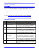
36 Troubleshooting
A Motor Over Temp Axis 2 Normally-closed input on the front of the GEO drive amplifier
connector X3 is detected in open circuit between pins 3 and 4.
B Over Voltage. The bus voltage has exceeded a factor pre-set threshold of 820V for
480V drives or 420V for 230V drives. Lack of ability to dump the
regenerated energy from the motor. A shunt regulator or dump resistor
can help GAR 49 or GAR78. Another common cause can be
excessively high input line voltage.
C Under Voltage The DC bus internal to the GEO drive has decreased below a factory
pre-set threshold of 16 to 30Vdc (no AC input power to the drive).
D Shunt Regulator Fault Fatal fault where the internal drive electronics for the power stage that
controls the shunt regulator has failed. If unable to reset this fault, the
unit needs to be returned to the factory for repair.
A short in the shunt regulator or motor leads can cause this fault code.
The output drive transistors have gone into a linear mode instead of a
switching mode (DSAT).
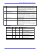
E Ground Fault A short in the shunt regulator or motor leads can cause this fault code.
The output drive transistors have gone into a linear mode instead of a
switching mode (DSAT).
F Gate Drive Power Fault Fatal fault where the internal drive electronics for the power stage that
controls the six IGB outputs has failed. If unable to reset this fault, the
unit needs to be returned to the factory for repair.
A short in the shunt regulator or motor leads can cause this fault code.
The output drive transistors have gone into a linear mode instead of a
switching mode (DSAT).
Status Display
Status Display
Color
Direct
PWM
MACRO
Description
7-segment LED Red Standard Standard 16 numeric codes plus two decimal
points
Enable 1 LED Green/Red Standard Standard Green when first axis enabled. Red when
drive is not enabled. (Unlit does not
necessarily mean fault.)
Enable 2 LED Green/Red Standard
for 2-axis
Standard
for 2-axis
Green when second axis enabled. Red
when drive is not enabled. (Unlit does
not necessarily mean fault.)
DC bus LED Red Standard Standard Lit when bus powered.
Shunt LED Yellow Standard Standard Lit when drive is attempting to dump
power through the external shunt
regulator regen resistor.
+5V LED Green Standard Standard Lit when 5V logic has power.