^1 INSTALLATION MANUAL ^2 Geo Direct PWM Amplifier ^3 Direct PWM Amplifier ^4 500-603700-xIxx ^5 November 15, 2013 Single Source Machine Control ……………………………………………..…...………………. Power // Flexibility // Ease of Use 21314 Lassen St. Chatsworth, CA 91311 // Tel. (818) 998-2095 Fax. (818) 998-7807 // www.deltatau.
Copyright Information © 2013 Delta Tau Data Systems, Inc. All rights reserved. This document is furnished for the customers of Delta Tau Data Systems, Inc. Other uses are unauthorized without written permission of Delta Tau Data Systems, Inc. Information contained in this manual may be updated from time-to-time due to product improvements, etc., and may not conform in every respect to former issues. To report errors or inconsistencies, call or email: Delta Tau Data Systems, Inc.
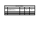
REVISION HISTORY REV.
Geo Direct PWM Amplifier Table of Contents INTRODUCTION .....................................................................................................................6 SPECIFICATIONS ...................................................................................................................7 PART NUMBER .............................................................................................................................7 ENVIRONMENTAL SPECIFICATIONS ....................................
Geo Direct PWM Amplifier PWM FREQUENCY .............................................................................................................. 36 POWER PMAC3 DRIVE SETUP .......................................................................................... 37 KEY GATE PARAMETERS ............................................................................................................ 37 KEY CHANNEL PARAMETERS .....................................................................................
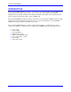
Geo Direct PWM Amplifier INTRODUCTION The Geo Direct PWM amplifiers provide a 1- or 2-axis motor power using highly integrated IGBT based power circuitry. They support a wide variety of motors and power ranges. The Geo Direct PWM amplifiers interface directly with Delta Tau’s PMAC2 or PMAC3 style digital ASICs, typically found in the axis expansion cards inside a Turbo or Power UMAC rack.
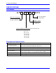
Geo Direct PWM Amplifier SPECIFICATIONS Part Number GP 000 0 = No Safety Relay 1 = Safety Relay Main AC Voltage Input: L = 115 - 230 VAC H = 300 - 480 VAC Number of Axes: 1 = Single Axis 2 = Dual Axis Continuous/Peak Current Rating (Sinusoidal Amp rms) 01 = 1.5 / 4.
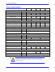
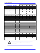
Geo Direct PWM Amplifier Electrical Specifications 230 VAC Drives – Single Axis GxL051 GxL101 GxL151 GxL201 GxL301 Main Input Power Main AC Input [VAC rms] Rated Input Current @ 240VAC 3ɸ [A rms] Frequency [Hz] Rated Input Power [Watts] Main Bus Capacitance [µf] 110-20% – 240+10% (~87 – 264) 3.3 6.6 9.9 13.2 19.
Geo Direct PWM Amplifier 230 VAC Drives – Dual Axis GxL012 GxL032 GxL052 GxL102 GxL152 Main Input Power Main AC Input [VAC rms] Rated Input Current @ 240VAC 3ɸ [A rms] Frequency [Hz] Rated Input Power [Watts] Main Bus Capacitance [µf] 110-20% – 240+10% (~87 – 264) 1.98 3.96 6.6 13.2 19.8 5259 7888 50/60 Hz 789 1578 2629 3380 5020 1Φ or 3Φ AC Input Phase Requirement 3Φ Output Continuous Current Output per Axis [A rms] 1.
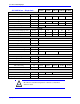
Geo Direct PWM Amplifier 480 VAC Drives – Single Axis GxH051 GxH101 GxH151 GxH201 GxH301 Main Input Power Main AC Input [VAC rms] Rated Input Current [A rms] Frequency [Hz] Rated Input Power [Watts] Main Bus Capacitance [µf] 375-20% – 480+10% (~300 – 525) 3.3 6.6 9.9 13.2 19.
Geo Direct PWM Amplifier 480 VAC Drives – Dual Axis GxH012 GxH032 GxH052 GxH102 GxH152 Main Input Power Main AC Input [VAC rms] Rated Input Current @ 240VAC 3ɸ [A rms] Frequency [Hz] Rated Input Power [Watts] Main Bus Capacitance [µf] 375-20% – 480+10% (~300 – 525) 1.98 3.96 6.6 13.2 19.8 10974 16461 50/60 Hz 1646 3292 5487 845 1255 1Φ or 3Φ AC Input Phase Requirement 3Φ Output Continuous Current Output per Axis [A rms] 1.
Geo Direct PWM Amplifier RECEIVING AND UNPACKING Delta Tau products are thoroughly tested at the factory and carefully packaged for shipment. When the Geo Direct PWM Drive is received, there are several things to be done immediately: Observe the condition of the shipping container and report any damage immediately to the commercial carrier that delivered the drive. Remove the drive from the shipping container and remove all packing materials.
Geo Direct PWM Amplifier MOUNTING, PHYSICAL LAYOUT The location of the Geo Direct PWM Drive is important. Installation should be in an area that is protected from direct sunlight, corrosives, harmful gases or liquids, dust, metallic particles, and other contaminants. Exposure to these can reduce the operating life and degrade performance of the drive.
Geo Direct PWM Amplifier GPx012 Width Height Depth Weight 3.30 in. / 84 mm 11.00 in. / 280 mm 5.80 in. / 147 mm 4.2 lbs / 1.9 kgs Low Profile, Single Width, No Fan W V U MOTOR 2 (J3) W V U MOTOR 1 (J2) EXT SHUNT (J5) REGEN + REGEN - 2.7” (68.6 mm) GATE ENABLE PWM INPUT 2 (X2) PWM INPUT 1 (X1) 10.625” (269.875 mm) 9.875” (250.825 mm) AMP STATUS DC BUS (D1) ENABLE 2 ENABLE 1 SHUNT +5V WARNING! Residual Voltage. Wait 5 minutes after removing power before servicing unit.
Geo Direct PWM Amplifier GPL032 Width Height Depth Weight 3.30 in./ 84 mm 11.00 in./ 280 mm 8.00 in./ 203 mm 5.4 lbs/ 2.45 kgs Single Width, No Fan W V U MOTOR 2 (J3) W V U MOTOR 1 (J2) EXT SHUNT (J5) REGEN + REGEN - 2.7” (68.6 mm) GATE ENABLE PWM INPUT 2 (X2) PWM INPUT 1 (X1) 10.625” (269.875 mm) 9.875” (250.825 mm) AMP STATUS DC BUS (D1) ENABLE 2 ENABLE 1 SHUNT +5V WARNING! Residual Voltage. Wait 5 minutes after removing power before servicing unit.
Geo Direct PWM Amplifier GPx05x, GPx102, GPL101, GPH032 Width Height Depth Weight 3.30 in./ 84 mm 11.00 in./ 280 mm 8.00 in./ 203 mm 5.5 lbs/ 2.5 kgs Single Width with Fan W V U MOTOR 2 (J3) W V U MOTOR 1 (J2) EXT SHUNT (J5) REGEN + REGEN - 2.7” (68.6 mm) GATE ENABLE PWM INPUT 2 (X2) 9.875” (250.825 mm) 10.625” (269.875 mm) PWM INPUT 1 (X1) AMP STATUS DC BUS (D1) ENABLE 2 ENABLE 1 SHUNT +5V WARNING! Residual Voltage. Wait 5 minutes after removing power before servicing unit.
Geo Direct PWM Amplifier GPx201, GPx301, GPx152, GPH102 Width Height Depth Weight 6.50 in./ 165 mm 11.00 in./ 280 mm 8.00 in./ 203 mm 11.5 lbs/ 5.2 kgs Double Width, Two Fans 5.860” (148.844 mm) 10.625” (269.875 mm) 9.875” (250.825 mm) 6.46” (164.084 mm) Mounting, Physical Layout 8” (203.
Geo Direct PWM Amplifier CONNECTOR PINOUTS AND WIRING WARNING Installation of electrical control equipment is subject to many regulations including national, state, local, and industry guidelines and rules. General recommendations can be stated but it is important that the installation be carried out in accordance with all regulations pertaining to the installation. J1: Main Bus Power Input J1 is used to bring the main AC/DC bus power into the Geo Direct PWM Drive.
Geo Direct PWM Amplifier AC input wires must be twisted together to eliminate as much noise radiation as possible. Note Recommended Main Bus Power Wiring/Protection Caution Main bus power lines should run in a separate duct (at least 12” or 30 cm away) from and should never be bundled with the I/O signal, communication, or encoder cables. Grounding, Bonding System grounding is crucial for proper performance of the Geo Direct PWM Drive.
Geo Direct PWM Amplifier Three-Phase Main AC Power Wiring Diagram GND L1 L2 L3 Shielded And Twisted EMC/EMI FILTER L2 L3 FUSE FUSE PROTECTION EARTH GND L1 FUSE 3-PHASE TRANSFORMER 110-240 VAC MAGNETIC CONTACTOR Phase-Phase Voltage Suppressors Single-Phase Main AC Power Wiring Diagram Single Phase Source 110-240 VAC FUSE PROTECTION EARTH Line FUSE GND Neutral GND L2 L3 Shielded And Twisted Note EMC/EMI FILTER MAGNETIC CONTACTOR Phase-Phase Voltage Suppressors If the Geo Direct PWM
Geo Direct PWM Amplifier Transformers Y-Y or Y- transformers should be used. - Transformers are NOT advised. They try to balance phases dynamically, creating instances of instability in the Geo Direct PWM Drive’s rectifying circuitry. Note A line reactor should be installed if a transformer or reliable source of power is not available. Line reactors suppress harmonics bidirectionally, eliminating low frequency spikes.
Geo Direct PWM Amplifier Recommended Bus Power Fuse and Wire Gauge Geo Drive electronics create a DC bus by rectifying the incoming AC lines. The current flow into the drive is not sinusoidal but rather a series of narrow, high-peak pulses. Keep the incoming impedance small so that these current pulses are not hindered. Conductor size, transformer size, and fuse size recommendations may seem larger than normally expected.
Geo Direct PWM Amplifier J4: 24 VDC Logic Control J4 is used to bring the 24VDC logic power into the Geo Direct PWM Drive. This power can remain on, regardless of the main AC/DC bus power input, allowing the digital control electronics to be active while the main motor power control is passive. It is recommended to use a protected power supply. In situations where the power supply is shared with other devices, it may be desirable to insert a filter before applying it to the Geo Direct PWM Drive.
Geo Direct PWM Amplifier J2 – J3: Motor Wiring The cable wiring must be shielded and have a separate conductor connecting the motor frame back to the Geo Direct PWM Drive’s chassis.
Geo Direct PWM Amplifier The motor thermostats are brought in through connector X3. Note Motor Cable, Noise Elimination The Geo Direct PWM Drives’ voltage output has a fundamental frequency and amplitude that corresponds to motor speed, torque, and number of poles. The Geo Direct PWM Drive produces higher frequency voltage components corresponding to the rise, fall and repetition rate of the fast switching PWM signals. Subsequently, it could naturally couple current noise to nearby conductors.
Geo Direct PWM Amplifier Note Ferrite cores are also commonly used with lower inductance motors to enhance compatibility with the Geo Direct PWM Drive, which is specified to a minimum of 2 mH. Do not use a motor wire gauge less than 14 AWG for 5/10A or 8/16A axes, and 10 AWG for 15/30A or 30/60A axes unless otherwise specified by the motor manufacturer. Refer to Motor manufacturer and local code recommendations. Avoid running sensitive signal cables (i.e.
Geo Direct PWM Amplifier Motor Torque Torque requirements in an application can be viewed as both instantaneous and average Typically, the instantaneous or peak torque is the sum of machining, and frictional forces required to accelerate the inertial load. The energy required to accelerate a load follows the equation T=JA where T is the torque, J is the inertia, and A is the acceleration.
Geo Direct PWM Amplifier J5: External Shunt Resistor J5 is used to wire an external shunt resistor to expel the excess power during demanding deceleration profiles. These shunt resistors are designed to drain excess bus energy very quickly. All applications using Geo direct PWM Drives (all configurations) are strongly advised to install an external shunt resistor.
Geo Direct PWM Amplifier The black wires are for the thermostat and the white wires are for the shunt resistor. Hot! The shunt resistor incorporates a normally closed (N.C) thermal overload protection thermostat that opens up when the core temperature of the resistor exceeds 225°C (450° F). This thermostat is accessible through the two black leads. It is important that these two leads be wired in a safety circuit to halt operation should the resistor temperature exceed the specified threshold.
Geo Direct PWM Amplifier Shunt Resistor Layout Connector PinOuts and Wiring 30
Geo Direct PWM Amplifier X1 – X2: PWM Connectors This mini D36 connector provides the interface to the PWM output channel from the controller (PMAC).
Geo Direct PWM Amplifier X3: Discrete I/O for Motor Thermals This 6-pin Phoenix Contact terminal block provides connectivity to low impedance 12 – 24 VDC motor thermostat overload detection. This is a normally closed contact, in normal mode operation the Geo direct PWM Drive expects to see 12 – 24 VDC coming into Pins #1 and #3 respectively for motors 1 and 2.
Geo Direct PWM Amplifier X4: Safety Relay This 4-pin Phoenix Contact Terminal Block provides connectivity to a safety relay input, and If the Safety Relay option is installed, there is a dedicated Safety Input @24VDC (user supplied). When the Safety Input is asserted, then the hardware will cut the 20V power to the gate driver which will prevent all output from the power stage (the Gate Enable LED will turn off).
Geo Direct PWM Amplifier POWER ON/OFF PROCEDURES Changing the ADC clock on the controller (PMAC) side requires recycling power on the Geo Direct PWM Drive. Caution Main bus power should NEVER be applied if the 24V logic power is NOT applied. Caution Caution Make sure that no motor commands (e.g. phasing, jogging, or open loop) are being executed by or sent by the controller (PMAC) at the time of applying main bus power. Powering up the Geo Direct PWM Drive must obey the following procedure: 1. 2. 3.
Geo Direct PWM Amplifier If the main bus power is removed (i.e. E-Stop condition), it is necessary to keep it off until the Bus LED is turned off or dimmed completely. About 5-6 minutes. This ensures that the capacitors’ voltage has dropped below 97 VAC and that the soft start circuitry has been armed. Main bus power should Not be recycled within a time range of about ~ 5 minutes.
Geo Direct PWM Amplifier PWM FREQUENCY The minimum PWM frequency of a system is based on the time constant of the motor. In general, the lower the time constant, the higher the PWM frequency should be. The motor time constant is calculated dividing the motor inductance by the resistance (phase-phase). The minimum PWM Frequency is then determined using the following relationship: ; => Example: A motor with an inductance of 6.1 millihenries (mH), and a resistance of 11.
Geo Direct PWM Amplifier POWER PMAC3 DRIVE SETUP Caution The ADC Strobe Word, Gate3[i].AdcAmpStrobe, must be set to $FFFFFC for proper operation in default mode. Failure to do so could result in damage to the amplifier. Key Gate Parameters The following Gate-specific parameters are essential for the proper software setup of the Geo Direct PWM Drive: Structure Element Description Typical/Default Sys.WpKey PMAC3 Write Protection 0 Gate3[i].PhaseFreq Phase Frequency Gate3[i].
Geo Direct PWM Amplifier Key Channel Parameters The following channel-specific parameters are essential for the proper software setup of the Geo Direct PWM Drive: Structure Element Description Typical/Default Notes Gate3[i].Chan[j].PwmFreqMult PWM Frequency 0 4.5 KHz PWM Motor[x].ServoCtrl Activate channel 1 Motor[x].PhaseCtrl Commutation enable 1 With PackInData = 0 Motor[x].PhaseOffset Commutation Phase angle -683 -512 for Brush Motor Motor[x].
Geo Direct PWM Amplifier Trying to enable the Geo Direct PAM Drive with misreported current data could result in damaging the electronics of the Drive. Caution At this point of the drive-motor setup, and before tuning the current loop, a couple of sanity checks can be performed, making sure that: Enabling the drive with a #nOut0 command does not produce any faults in neither the drive nor the PMAC. The current sensors are operating properly by monitoring the current measurements (i.e. Motor[x].
Geo Direct PWM Amplifier POWER PMAC2 DRIVE SETUP Caution The ADC Strobe Word, Gate1[i].AdcStrobe, must be set to $3FFFFF for proper operation in default mode. Failure to do so could result in damage to the amplifier. Key Gate Parameters The following Gate-specific parameters are essential for the proper software setup of the Geo Direct PWM Drive: Structure Element Description Gate1[i].PwmPeriod PWM Frequency Gate1[i].PhaseClockDiv Typical/Default Notes 6527 4.
Geo Direct PWM Amplifier Key Channel Parameters The following channel-specific parameters are essential for the proper software setup of the Geo Direct PWM Drive: Structure Element Description Typical/Default Motor[x].ServoCtrl Activate channel 1 Motor[x].PhaseCtrl Commutation enable 1 Motor[x].PhaseOffset Commutation Phase angle 683 Motor[x].pAdc Current Feedback Address Pointer Motor[x].AdcMask ADC Mask Motor[x].PwmSf PWM Scale Factor Motor[x].
Geo Direct PWM Amplifier Trying to enable the Geo Direct PAM Drive with misreported current data could result in damaging the electronics of the Drive. Caution At this point of the drive-motor setup, and before tuning the current loop, a couple of sanity checks can be performed, making sure that: Enabling the drive with a #nOut0 command does not produce any faults in neither the drive nor the PMAC. The current sensors are operating properly by monitoring the current measurements (i.e. Motor[x].
Geo Direct PWM Amplifier TURBO PMAC2 DRIVE SETUP Caution The ADC Strobe Word, I7m06 ($C014 in Non-Turbo PMAC), must be set to $3FFFFF for proper operation in default mode. Failure to set I7m06 equal to $3FFFFF could result in damage to the amplifier. Key Gate Parameters The following Gate-specific parameters are essential for the proper software setup of the Geo Direct PWM Drive: Turbo Non-Turbo Description I7m00 I900 Max phase clock I7m01 I901 I7m02 Typical/Default Notes 6527 4.
Geo Direct PWM Amplifier Key Channel Parameters The following channel-specific parameters are essential for the proper software setup of the Geo Direct PWM Drive: Variable Description Typical/Default Ixx00 Activate channel 1 Ixx01 Commutation enable 1 Ixx72 Commutation Phase angle 683 Ixx82 Current Feedback Address Address Location Ixx84 ADC Mask Ixx66 PWM Scale Factor Ixx57 Continuous current limit Ixx58 Integrated current limit Ixx69 Maximum command output Ixx61 Integral gain I
Geo Direct PWM Amplifier I2T Settings, Ixx57, Ixx58, and Ixx69 Example: #define #define #define #define #define ServoClk ContCurrent PeakCurrent MaxADC I2TOnTime 2.258 3 9 16.26 2 ; ; ; ; ; Servo Clock [KHz]—computed in Dominant Clock Settings Section Continuous Current Limit [Amps] -User Input Instantaneous Current Limit [Amps] -User Input =16.26 for 5/10A -User Input, see electrical specs Time allowed at peak Current [sec] -User Input I157 = INT(32767*(ContCurrent*1.
Geo Direct PWM Amplifier DRIVE COMMAND STRUCTURE Default Mode In default mode, the Geo Direct PWM Drive returns phases A and B current measurements as well as global and axis faults. Failure to set the ADC strobe word correctly could result in damaging the drive’s electronics.
Geo Direct PWM Amplifier Enhanced Mode Enhanced mode enables access to and control of additional functions: Bus voltage reading IGBT temperature(s) reading Set PWM control for brush motor Turn Line Monitor off The drive must be put in enhanced mode before accessing the additional functions. Caution Once the drive is set up for enhanced mode, do not set it back to default mode until the next logic power cycle.
Geo Direct PWM Amplifier And the data is found in the lower 12 bits of ADC B for each axis: PMAC Type ADC B data register Non-Turbo Y:$C006 Turbo Mxx06 Power PMAC2 Gate1[i].Chan[j].Adc[1] Power PMAC3 Gate3[i].Chan[j].
Geo Direct PWM Amplifier TROUBLESHOOTING LED Status LED Description ENABLE 1 Green when axis 1 is enabled Red when axis 1 is not enabled Unlit does not necessarily mean a faulty condition ENABLE 2 Green when axis 2 is enabled Red when axis 2 is not enabled Unlit does not necessarily mean a faulty condition Red when bus is connected (capacitors are charged) Unlit when bus is not connected (capacitors fully discharged) BUS SHUNT Yellow when the drive is dissipating power Unlit when
Geo Direct PWM Amplifier Error Codes Display Code AXIS 1 AXIS 2 Troubleshooting Error / Fault Description Description Over Current RMS Indicates that the I2T model, hard-coded in the amplifier processor projecting current output over time, has been violated within the operating current specification range of the amplifier. Over Current Peak Indicates that an excessive amount of current (exceeding the specs of the amplifier) has been detected through the motor leads.
Geo Direct PWM Amplifier Display Code Error / Fault Description Troubleshooting Notes GLOBAL Normal Mode Operation No faults reported Over Voltage The bus voltage has exceeded the permissible threshold: 420 VAC for GPL Drives 820 VAC for GPH Drives Make sure that the external shunt is connected properly. Make sure that the AC input is not excessively over spec. Under Voltage No bus voltage input. Bus voltage has dropped below the permissible threshold (97 VAC).
Geo Direct PWM Amplifier APPENDIX A: CABLE/CONNECTOR KITS PWM Cables Option Cable Length Part Number CABPWM-1 24” (600 mm) 200-602739-024X CABPWM-2 36” (900 mm) 200-602739-036x CABPWM-3 60” (1.5 m) 200-602739-060x CABPWM-4 72” (1.8 m) 200-602739-072x CABPWM-5 84” (2.1 m) 200-602739-084x CABPWM-6 144” (3.6 m) 200-602739-144x PWM cables are compatible with all models of the Geo Direct PWM Drives.
Geo Direct PWM Amplifier Cable Kits Part Number Model CABKIT1B Gxx012xx Gxx032xx Gxx052xx GxL102xx Molex mating connectors pre-crimped for 2 axes: 3 ft. AC Input Cable 3 ft. 24 VDC Power Cable 10 ft. shielded Motor Cables Gxx051xx Molex mating connectors pre-crimped for 1 axis: 3 ft. AC Input Cable 3 ft. 24 VDC Power Cable 10 ft. shielded Motor Cables GxH102xx Gxx152xx Molex mating connectors pre-crimped for 2 axes: 3 ft. AC Input Cable 3 ft. 24 VDC Power Cable 10 ft.