
Installation manual

Geo Direct PWM Amplifier
Connector PinOuts and Wiring 18
CONNECTOR PINOUTS AND WIRING
WARNING
Installation of electrical control equipment is subject to many
regulations including national, state, local, and industry guidelines
and rules. General recommendations can be stated but it is
important that the installation be carried out in accordance with
all regulations pertaining to the installation.
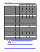
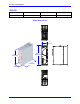
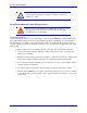
J1: Main Bus Power Input
J1 is used to bring the main AC/DC bus power into the Geo Direct PWM Drive.
J1: Molex 3-pin Female
Mating: Molex 3-pin Male
L1
L2
L3
Tie Ground to
chassis stud
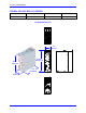
Pin #
Symbol
Function
Three Phase
Single Phase
DC
1
L3
Input
AC Line Phase 3
Line
DC+
2
L2
Input
AC Line Phase 2
Neutral
DC Return
3
L1
Input
AC Line Phase 1
Not connected
Not connected
DT Housing pn: 014-H00F03-049
DT Pins pn: 014-042815-0031
Molex housing pn: 42816-0312
Molex pins pn: 42815-0031
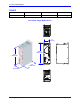
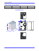
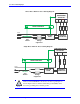
GPx201 and GPx301
J1: Molex 4-pin Female
Mating: Molex 4-pin Male
L3
L2
L1
GND
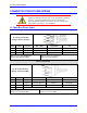
Pin #
Symbol
Function
Three Phase
Single Phase
DC
1
L3
Input
AC Line Phase 3
Line
DC+
2
L2
Input
AC Line Phase 2
Neutral
DC Return
3
L1
Input
AC Line Phase 1
Not connected
Not connected
4
GND
Common Ground
DT Housing pn: 014-H00F04-049
DT Pins pn: 014-042815-0031
Molex housing pn: 42816-0412
Molex pins pn: 42815-0031