
Installation manual

Geo Direct PWM Amplifier
Connector PinOuts and Wiring 31
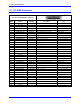
X1 – X2: PWM Connectors
This mini D36 connector provides the interface to the PWM output channel from the controller (PMAC).
X1 – X2: 36-Pin Mini-D Connector
Pin#
Symbol
Function
Description
Notes
1
Reserved
2
Reserved
3
ADC_CLK1+
Command
A/D converter clock
4
ADC_STB1+
Command
A/D converter strobe
5
CURRENT1A+
Feedback
Phase A actual current data
Serial digital
6
CURRENT1B+
Feedback
Phase B actual current data
Serial digital
7
AENA1+
Command
Amplifier enable
High is enable
8
FAULT1+
Feedback
Amplifier fault
High is fault
9
PWMATOP1+
Command
Phase A top cmd
High is on command
10
PWMABOT1+
Command
Phase A bottom cmd
High is on command
11
PWMBTOP1+
Command
Phase B top cmd
High is on command
12
PWMBBOT1+
Command
Phase B bottom cmd
High is on command
13
PWMCTOP1+
Command
Phase C top cmd
High is on command
14
PWMCBOT1+
Command
Phase C bottom cmd
High is on command
15
GND
Common
Reference voltage
16
+5V
Power
+5V Power
From controller
17
Reserved
18
Reserved
19
Reserved
20
Reserved
21
ADC_CLK1-
Command
A/D converter clock
22
ADC_STB1-
Command
A/D converter strobe
23
CURRENT1A-
Feedback
Phase A actual current DATA
Serial digital
24
CURRENT1B-
Feedback
Phase B actual current DATA
Serial digital
25
AENA1-
Command
Amplifier enable
Low is enable
26
FAULT1-
Feedback
Amplifier fault
Low is fault
27
PWMATOP1-
Command
Phase A top cmd
Low is on command
28
PWMABOT1-
Command
Phase A bottom cmd
Low is on command
29
PWMBTOP1-
Command
Phase B top cmd
Low is on command
30
PWMBBOT1-
Command
Phase B bottom cmd
Low is on command
31
PWMCTOP1-
Command
Phase C top cmd
Low is on command
32
PWMCBOT1-
Command
Phase C bottom cmd
Low is on command
33
GND
Common
Reference Voltage
34
+5V
Power
+5V Power
From controller
35
Reserved
36
Reserved