
Installation manual

Geo Direct PWM Amplifier
Troubleshooting 49
TROUBLESHOOTING
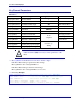
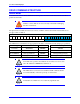
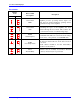
LED Status
LED
Description
ENABLE 1
Green when axis 1 is enabled
Red when axis 1 is not enabled
Unlit does not necessarily mean a faulty condition
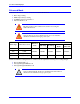
ENABLE 2
Green when axis 2 is enabled
Red when axis 2 is not enabled
Unlit does not necessarily mean a faulty condition
BUS
Red when bus is connected (capacitors are charged)
Unlit when bus is not connected (capacitors fully discharged)
SHUNT
Yellow when the drive is dissipating power
Unlit when the drive is not dissipating (most cases)
+5V
Green when 5 VDC power is present
Unlit indicates that the 5VDC is not present (failure condition)
GATE ENABLE
Green when the gate is enabled
Unlit when the gate is disabled
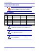
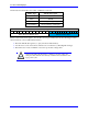
7-Segment Display
The Global and Axis faults are interpreted by the Amplifier processor(s) and sent to the 7-
segment 3-character scrolling display (D1 amp status).
The blinking dot is the heartbeat of the drive processor(s) and is always active in normal
mode operation. It is turned off or not blinking when the drive is in reset mode (reloading
firmware) or has no logic power.
The display is blank if there are no axes enabled, and no faults. It shows a 0 if any of the axes are enabled,
this is the normal mode operation. Not all errors reflect a message back to the PMAC. In these cases, the
error is only sent to the Status Display.
Note
The Geo Drive disables (kills the output to the motors) automatically
at the occurrence of a fault.
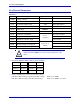
The response of the Geo Drive to an error depends on the error's severity. There are two levels of severity:
Warnings, simply called errors and not considered faults. They do not disable operation.
Fatal errors which disable the drive’s output to the motors, occasionally communication to PMAC