^1 USER MANUAL ^3U03U042 Geo 3U Direct PWM Drive (New Version) ^3 Geo 3U Direct PWM Drive, 3U042 ^4 5xx-603729-xUx2 ^5 July 26, 2006 Single Source Machine Control Power // Flexibility // Ease of Use 21314 Lassen Street Chatsworth, CA 91311 // Tel. (818) 998-2095 Fax. (818) 998-7807 // www.deltatau.
Copyright Information © 2006 Delta Tau Data Systems, Inc. All rights reserved. This document is furnished for the customers of Delta Tau Data Systems, Inc. Other uses are unauthorized without written permission of Delta Tau Data Systems, Inc. Information contained in this manual may be updated from time-to-time due to product improvements, etc., and may not conform in every respect to former issues. To report errors or inconsistencies, call or email: Delta Tau Data Systems, Inc.
Safety Instructions Qualified personnel must transport, assemble, install, and maintain this equipment. Properly qualified personnel are persons who are familiar with the transport, assembly, installation, and operation of equipment. The qualified personnel must know and observe the following standards and regulations: IEC 364 resp.
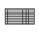
REVISION HISTORY REV. 1 DESCRIPTION REPLACED COVER PRODUCT PHOTO DATE CHG APPVD 07/25/06 CP D.
3U Servo Amplifier Table of Contents Copyright Information................................................................................................................................................i Operating Conditions .................................................................................................................................................i Safety Instructions........................................................................................................................
3U Servo Amplifier Wiring the Motor Thermostats ................................................................................................................................24 Motor Temperature Switch .................................................................................................................................24 GEO 3U PWM BACKPLANE CONNECTIONS...................................................................................................25 3UBP8A, 300-603730-10x....................
3U Servo Amplifier Table of Contents iv
3U Servo Amplifier Table of Contents v
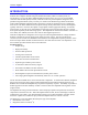
3U Servo Amplifier INTRODUCTION This document provides user data and support for the 3U Geo Direct PWM drives 3U042. Geo drives are brushless drive amplifier modules designed and manufactured by Delta Tau Data Systems, Inc. The 3U042 is a 3U size Geo Direct PWM amplifier designed to drive up to two axis with 4A RMS continuous and 8A RMS peak (2 seconds).
3U Servo Amplifier • • • • • • • • Motor over temperature (input from motor) Under voltage IGBT thermal failure PWM fault Over voltage Ground fault Minimum dead time protection Shoot through protection Note: The 3U drive products are available in kit-form. The electronics on these products are subject to damage by static electricity. Handle it as little as possible. Use ground wrist straps when handling. Do not allow static-charge holding materials (paper, plastic, etc.
3U Servo Amplifier current required by the amplifier. A little extra room should be given to this parameter to allow for good servo control. Most applications have a duty cycle in which the acceleration profile occurs repetitively over time. Calculating the average value of this profile gives the continuous rating required by the amplifier. Applications also concern themselves with the ability to achieve a speed.
3U Servo Amplifier can drive any range of back EMF motor, but the back EMF is highly related to the other parameters of the motor such as the motor inductance and the motor Kt. It is the back EMF of the motor that limits the maximum achievable speed and the maximum horsepower capability of the motor. Motor Torque Constant Motor torque constant is referred to as Kt and usually it is specified in torque-per-amp. It is this number that is most important for motor sizing.
3U Servo Amplifier RECEIVING AND UNPACKING Delta Tau products are thoroughly tested at the factory and carefully packaged for shipment. When the 3U Geo Direct PWM Drive is received, there are several things to be done immediately: 1. Observe the condition of the shipping container and report any damage immediately to the commercial carrier that delivered the drive. 2. Remove the control from the shipping container and remove all packing materials.
3U Servo Amplifier Electrical Specifications Output Circuits (axes) Nominal Input Voltage (VAC) Rated Input Voltage (VAC) Rated Continuous Input Current (A ACRMS) Rated Input Power (Watts) Frequency (Hz) Phase Requirements Charge Peak Inrush Current (A) Main Bus Capacitance (µf), backplane board Rated Output Voltage (V) Rated Cont.
3U Servo Amplifier Physical Specifications L x W x H (inches) Width (3U rack slots) Weight: drive only with front panel (w/o backplane and side panels) Backplane Backplane Width (3U rack slots) Backplane Weight Terminal Connections Backplane Board 3U042 6.30 x 2.40 x 5.08 3 0.9kgs (2.0lbs) 3UBP8A 3 0.275kgs (0.
3U Servo Amplifier MOUNTING The 3U Geo Direct PWM drives are designed to be installed in an enclosure whose ambient temperature does not exceed 55 °C. It must not be exposed to conductive dust or humidity in excess of 90% noncondensing. Corrosive gasses, corrosive dust, and other contaminants must be kept out of the drive enclosure. 6.30 2.39 DELTA TAU 2-AXIS PWM AMPLIFIER 230 VAC INPUT - 4A rms CONT/8A rms PEAK MOTOR O.T .
3U Servo Amplifier SYSTEM WIRING GARxx SHUNT RESISTOR EARTH BLOCK WHT Motor#1 3U042 Geo Direct PWM drive BLK BLK WHT BLU WHT GRN\YEL SCREW HEAD EARTH FRAME Optional EMI FILTER Motor#2 BLK U V W Motor #2 MCR BLK U V W Motor #1 MAIN POWER BLU WHT 3UBP8A Backplane 300-603730 -10x TB1 Fusing L2 L1 24V POWER SUPPLY +24 V RED Twisted Wires 24 V RET BLK BLK RED AC INPUT L3 Twisted Wires FAN J3 GND 24V J2 GND +24V TB2 SHUNT EARTH SHUNT RTN WARNING: Installation of electrical con
3U Servo Amplifier over size to keep the impedances of these inserted devices from affecting stated system performance. In general, it is recommended that all single-phase systems up to 1kW be designed for a 50% overload. All single-phase systems over 1kW should be designed for a 200% overload capacity. Noise Problems When problems do occur often it points to electrical noise as the source of the problem. When this occurs, turn to controlling high-frequency current paths.
3U Servo Amplifier Amplifier Cooling Considerations The drive amplifiers produce heat that must be removed. The installation requires that a fan blows air up through the vertical fins of the product’s heat sink. The 3U Geo Direct PWM drive systems include the metal plates that go around the unit as part of the rack’s metal panel work and a 24VDC (2.6W) fan. The fan must be positioned at the bottom side of the drive unit and attached to the fan connector, J3 for 3U042, on the backplane for power.
3U Servo Amplifier as FRN-type fuses. Due to the various regulations of local codes, NEC codes, UL and CE requirements, it is very important to reference these requirements before making a determination of how the input power is wired. Additionally, many systems require that the power be able to be turned on and off in the cabinet. It is typical that the AC power is run through some kind of main control contact within the cabinet, through the fuses, and then fed to a Geo drive.
3U Servo Amplifier Wiring 24 V Logic Control An external 24VDC power supply is required to power the logic portion of the 3U Geo Direct PWM drive. This power can remain on, regardless of the main AC input power, allowing the signal electronics to be active while the main motor power control is inactive. The 24V is wired into connector J2 at the 3UBP8A backplane. The polarity of this connection is extremely important. Carefully follow the instructions in the wiring diagram.
3U Servo Amplifier Shunt Regulation When the motor is used to slow the moving load, this is called regenerative deceleration. Under this operation, the motor is acting as a generator consuming energy from the load while passing the energy into the DC Bus storage capacitors. Left unchecked, the DC Bus voltage can raise high enough to damage the drive. For this reason there are protection mechanisms built into the Geo Drive product such as shunt regulation and over-voltage protection.
3U Servo Amplifier In standard metric (SI) units, the kinetic energy of a linearly moving mass is: EK = 1 mv 2 2 where: EK is the kinetic energy in joules (J) m is the mass in kilograms (kg) v is the linear velocity of the mass in meters/second (m/s) Here also, to get energy in Joules from English mechanical units, additional conversion factors are required. To calculate the kinetic energy of a mass having a weight of W pounds, the following equation can be used: E K = 0.678 W 2 v = 0.
3U Servo Amplifier E LM = 0.
3U Servo Amplifier %on-time is the percentage of time the regen circuit is active Note: The Turn On voltage for the shunt circuitry for all Geo drives is 388.5V. There is a Hysteresis of 20V, so if the regen turns on @ 388.5V it will not turn off until it drops to 367.5V.
3U Servo Amplifier Bonding The proper bonding of shielded cables is imperative for minimizing noise emissions and increasing immunity levels. The bonding effect is to reduce the impedance between the cable shield and the back panel. Power input wiring does not require shielding (screening) if the power is fed to the enclosure via metal conduit. If metal conduit is not used in the system, shielded cable is required on the power input wires along with proper bonding techniques.
3U Servo Amplifier Motor lead noise is either common-mode or differential. The common-mode conducted currents occur between each motor lead and ground (line-to-neutral). Differential radiated currents exist from one motor lead to another (line-to-line). The filtering of the lines feeding the motor provides additional attenuation of noise currents that may enter surrounding cables and equipment I/O ports in close proximity. Differential mode currents commonly occur with lengthy motor cables.
3U Servo Amplifier Backplane Board 20
3U Servo Amplifier 3U DRIVE CONNECTIONS PWM Input Connector Axis #1 PWM input connector P1 (36-pin Mini-D Connector) Pin # Symbol Function Description Notes 1 2 3 4 5 6 7 8 9 10 11 12 13 14 15 16 17 18 19 20 21 22 23 FC0 Feedback 1 of 4 fault code bits FC2 Feedback 1 of 4 fault code bits ADC_CLK1+ Command A/D converter clock ADC_STB1+ Command A/D converter strobe CURRENTA+ Feedback Phase A actual current data Serial digital CURRENTB+ Feedback Phase B actual current data Serial digital AENA1+ Command
3U Servo Amplifier Axis #2 PWM Input connector P2 (36-pin Mini-D Connector) Pin # Symbol Function Description Notes 1 2 3 4 5 6 7 8 9 10 11 12 13 14 15 16 17 18 19 20 21 22 23 FC0 Feedback 1 of 4 fault code bits FC2 Feedback 1 of 4 fault code bits ADC_CLK2+ Command A/D converter clock ADC_STB2+ Command A/D converter strobe CURRENTA+ Feedback Phase A actual current data Serial digital CURRENTB+ Feedback Phase B actual current data Serial digital AENA2+ Command Amplifier enable High is enable FAULT2+ F
3U Servo Amplifier Motor Output Connector The cable wiring must be shielded and have a separate conductor connecting the motor frame back to the drive amplifier. The cables are available in cable kits (CABKIT3C) from Delta Tau. (See Appendix A.) Motor phases are conversed in one of three conventions. Motor manufacturers will call the motor phases A, B, or C. Other motor manufacturers call them U, V, W. Induction motor manufacturers may call them L1, L2, and L3. The drive’s inputs are called U, V, and W.
3U Servo Amplifier Wiring the Motor Thermostats Some motor manufacturers provide the motors with integrated thermostat overload detection capability. Typically, it is in one or two forms: a contact switch that is normally closed or a PTC. These sensors can be wired into the Geo drive's front panel MTR TEMPERATURE SWITCH. Motor 1 thermostat is wired to MTR1 PTC RET and MTR1 PTC. And Motor 2 thermostat can be wired to MTR2 PTC RET and MTR2 PTC.
3U Servo Amplifier GEO 3U PWM BACKPLANE CONNECTIONS 3UBP8A, 300-603730-10x J1 1 2 3 4 5 6 7 J3 8 F AN 9 RET J2 L3 + 24V L2 10 L1 11 SHUNT TB2 RET SHUNT TB1 EART H J1: 3U Geo Drive backplane slot J1: Connector Pin 1 2 3 4 5 6 7 8 9 10 11 Backplane Board Description BUS+/ Shunt+ BUS+/ Shunt+ SHUNT RTN BUSBUS+24V RTN +24V L3 3 phace AC input L2 3 phace AC input L1 3 phace AC input GND 25
3U Servo Amplifier J2: 24V Input Molex Connector J2: 24V Input Molex Connector .200 spacing, 22-30AWG Pin Description 1 +24VDC @ 1A 2 24V RETURN (GND) DeltaTau p/n: 200-C30F02-LHM MOLEX p/n: 10-01-3026(housing), 08-70-1028(pins) J3: FAN output Molex Connector J3: Fan Molex Connector .
3U Servo Amplifier Backplane Board 27
3U Servo Amplifier DIRECT PWM COMMUTATION CONTROLLER SETUP The 3U amplifier must have the proper controller setup to command the amplifier/motor system. This section summarizes the key variables of both Turbo and Non Turbo PMAC2 controllers that would have to be modified for use with the amplifier. The Delta Tau setup software such as Turbo Setup will help set these parameters for the system automatically.
3U Servo Amplifier DC BRUSH MOTOR DRIVE SETUP WITH NON-TURBO PMAC It is possible to use PMAC2’s direct PWM and digital current loop for control of DC brush motors, both those with permanent-magnet fields, and those with wound fields. Because PMAC2’s digital current loop and commutation algorithms are combined, it is necessary to activate PMAC2’s commutation algorithm for the motor, even though it is not commutating the motor.
3U Servo Amplifier • • • • • • • Ix78 = 0 for zero slip in the commutation calculations Ix81 = $80770: This tells PMAC2 to read the low 8 bits of Y:$0770 for the power-on phase position. This register is forced to zero on power-on/reset, so this setting forces the phase position to zero. Ix82 should contain the address of ADC B register for the feedback channel used (just as for brushless motors) when the ADC A register is used for the rotor (armature) current feedback.
3U Servo Amplifier DC BRUSH MOTOR DRIVE SETUP WITH TURBO PMAC Commutation Phase Angle: Ixx72 Ixx72 controls the angular relationship between the phases of a multiphase motor. When Turbo PMAC is closing the current loop digitally for Motor xx, the proper setting of this variable is dependent on the polarity of the current measurements.
3U Servo Amplifier • Ixx73 = 0, Ixx74 = 0: These default settings ensure that Turbo PMAC will not try to do a phasing search move for the motor. A failed search could keep Turbo PMAC from enabling this motor. • Ixx77 = 0 to command zero direct (field) current. • Ixx78 = 0 for zero slip in the commutation calculations. • Ixx82 should contain the address of ADC B register for the feedback channel used (just as for brushless motors) when the ADC A register is used for the rotor (armature) current feedback.
3U Servo Amplifier Before testing any of Turbo PMAC’s software features for digital current loop and direct PWM interface, it is important to know whether the hardware interface is working properly. PMAC’s M-Variables are used to access the input and output registers directly. The examples shown here use the suggested MVariable definitions for Motor 1.
3U Servo Amplifier Position Feedback and Polarity Test If the PWM command values observed in the Watch window are not zero, set them to zero with the command: M102=0 M104=0 M107=0 The motor can be turned (or pushed) freely by hand now. As the motor is turned, monitor the M101 value in the Watch window. Look for the following: • It should change as the motor is moved. • It should count up in one direction, and count down in the other direction.
3U Servo Amplifier PWM/ADC Phase Match Command values from Turbo PMAC’s Phase A PWM outputs should cause a roughly proportionate response of one sign or the other on Turbo PMAC’s Phase A ADC input (whatever the phase is named in the motor and drive). The same is true for Phase B.
3U Servo Amplifier SETTING I2T PROTECTION It is very important to set the I2T protection for the amplifier/motor system for PMAC2 direct PWM commutation. Normally, an amplifier has internal I2T protection because it is closing the current loop. When PMAC2 is closing the current loop, the amplifier cannot protect itself or the motor from over heating.
3U Servo Amplifier CALCULATING MINIMUM PWM FREQUENCY The minimum PWM frequency requirement for a system is based on the time constant of the motor. Calculate the minimum PWM frequency to determine if the amplifier will properly close the current loop. Systems with very low time constants need the addition of chokes or in-line inductive loads to allow the PMAC to properly close the current loop of the system. In general, the lower the time constant of the system, the higher the PWM frequency must be.
3U Servo Amplifier PWM DRIVE COMMAND STRUCTURE The amplifier functions in two modes: Default and Enhanced. Default Mode Default Mode is the mode the amplifier is in when it is first powered on or the power is re-cycled for any reason. Default mode is compatible with the full series of Delta Tau amplifiers and the A/D converters used on these amplifiers. In this mode, the amplifier returns not only the currents for phases A and B but also the fault codes for the axes associated with those currents.
3U Servo Amplifier TROUBLESHOOTING Error Codes In most cases, the Geo Drive communicates error codes with a text message via the serial port to the host. Some error codes are also transmitted to the Status Display. The same message is saved in the EEPROM under an error history log (FLTHIST, ERR) so nothing is lost when power is removed. Not all errors reflect a message back to the host. In these cases, the no-message errors communicate only to the Status Display.
3U Servo Amplifier Global Faults AF1 04 AF2 AF3 0B 0D AF4 0E AF5 AFb 0F 07 AFd 09 AFU 08 AFL 0C PWM over frequency fault – indicates the PWM frequency detected by the drive exceeds specified limits. Check your settings (I-vars) Strobe Word Fault – not valid strobe word $3FFFFF EEPROM Communication Fault – make sure the drive is properly grounded. If problem persists, send the drive for RMA. Shunt RMS Fault – The shunt will stay on continuously for only 2 seconds.
3U Servo Amplifier Amplifier stops and displays a code Amplifier Fault If a 3U amplifier displays other digit than 0, please refer to the appropriate table from above for an explanation of fault codes. Amplifier is dark If the amplifier status display, +5V, +12V, -12V, ENA1, and ENA2 are not illuminated, verify that DC bus is connected to the 3U amplifier.
3U Servo Amplifier APPENDIX A PWM Cable Ordering Information Cable Length 600mm 900mm 1.5m 1.8m (24") (36") (60") (72") 2.1m (84") 3.6m (144") √ CABPWM-1 CABPWM-2 CABPWM-3 CABPWM-4 CABPWM-5 CABPWM-6 √ √ √ √ √ Part Numbers 200-602739-024X 200-602739-036x 200-602739-060x 200-602739-072x 200-602739-084x 200-602739-144x Mating Connector and Cable Kits Cable sets can be purchased directly from Delta Tau to make the wiring of the system easier. Available cable kits (CABKITxx) are listed below.
3U Servo Amplifier Motor Cable Drawing 3U042 (CABKIT3C) Appendix B 43
3U Servo Amplifier APPENDIX B Regenerative Resistor: GAR78/48 Appendix B 44
3U Servo Amplifier Appendix B 45
3U Servo Amplifier APPENDIX C 3U Rack DIMENSIONS R E V IS IO N S DESCRIPTION REV . -- DATE NEWDRAWINGRELEASE 6-19- 03 CHGD APPROVED N.G . D.D . MINIMUM OF (1) 1 -SLOT BLANK FOLLOWED BY2-SLOT FILLERS MUST START W/1 1/4 -SLOT BLANK TOP VIEW A C B 8.580 2. 250 1. 475 1.