
User manual


3U Servo Amplifier
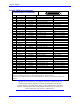
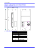
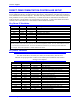
Axis #2 PWM Input connector
P2 (36-pin Mini-D Connector)
Pin # Symbol Function Description Notes
1 FC0 Feedback 1 of 4 fault code bits
2 FC2 Feedback 1 of 4 fault code bits
3 ADC_CLK2+ Command A/D converter clock
4 ADC_STB2+ Command A/D converter strobe
5 CURRENTA+ Feedback Phase A actual current data Serial digital
6 CURRENTB+ Feedback Phase B actual current data Serial digital
7 AENA2+ Command Amplifier enable High is enable
8 FAULT2+ Feedback Amplifier fault High is fault
9 PWMATOP2+ Command Phase A top Cmd High is on command
10 PWMABOT2+ Command Phase A bottom Cmd High is on command
11 PWMBTOP2+ Command Phase B top Cmd High is on command
12 PWMBBOT2+ Command Phase B bottom Cmd High is on command
13 PWMCTOP2+ Command Phase C top Cmd High is on command
14 PWMCBOT2+ Command Phase C bottom Cmd High is on command
15 GND Common Reference voltage
16 +5V Power +5v power From controller
17 Reserved
18 Reserved
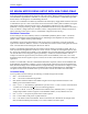
19 FC1 Feedback 1 of 4 fault code bits
20 FC3 Feedback 1 of 4 fault code bits
21 ADC_CLK2- Command A/D converter clock
22 ADC_STB2- Command A/D converter strobe
23 CURRENTA- Feedback Phase A actual current data Serial digital
24
CURRENTB- Feedback Phase B actual current data Serial digital
25 AENA2- Command Amplifier enable Low is enable
26 FAULT2- Feedback Amplifier fault Low is fault
27 PWMATOP2- Command Phase A top Cmd Low is on command
28 PWMABOT2- Command Phase A bottom Cmd Low is on command
29 PWMBTOP2- Command Phase B top Cmd Low is on command
30 PWMBBOT2- Command Phase B bottom Cmd Low is on command
31 PWMCTOP2- Command Phase C top Cmd Low is on command
32 PWMCBOT2- Command Phase C bottom Cmd Low is on command
33 GND Common Reference voltage
34 +5V Power +5v power From controller
35 Reserved
36 Reserved
A Mini-D 36-pin connector for first digital amplifier command outputs and current feedbacks. This
connector provides the interface to a fully digital amplifier for the first channel.
Note that current feedback data must be in serial digital form, already converted from analog in the
amplifier.
Note:
The dual axis unit, 3U042, has two jumpers on the logic board (603728-10x
/bottom board). If these Jumpers are ON then the shield of the PWM cable
connects directly to the GND, if the jumper is OFF (default) there is a 0.1mfd
capacitor in the way to the GND. These jumpers are E2 and E3, for channels #1
and #2 respectively. For revisions -104 and above.
Backplane Board 22