
User manual

3U Servo Amplifier
PWM DRIVE COMMAND STRUCTURE
The amplifier functions in two modes: Default and Enhanced.
Default Mode
Default Mode is the mode the amplifier is in when it is first powered on or the power is re-cycled for any
reason. Default mode is compatible with the full series of Delta Tau amplifiers and the A/D converters
used on these amplifiers.
In this mode, the amplifier returns not only the currents for phases A and B but also the fault codes for the
axes associated with those currents. The fault codes occupy the lower 12-bits on each phase.
For Default mode to work correctly, make sure that the A/D strobe word for the axis is set to the correct
value for the A/D on the amplifier. For instance, the current Delta Tau amplifiers use a 12-bit Burr
Brown part requiring a strobe word of $3FFFFF; this word is written to
X:$C014 as WX:$C014, $3FFFFF for non-Turbo. For Turbo PMAC I7m06= $3FFFFF.
This value can be saved to PMAC memory and sent to the amplifier on boot automatically.
Enhanced Mode
Enhanced mode is available on the Geo series of Delta Tau amplifiers and offers many more options.
Like the Default mode, Enhanced mode requires that a special strobe word be written to the amplifier, and
like Default mode, this word may be saved to PMAC memory and issued each boot automatically.
Enhanced mode axes and Default mode axes may not be mixed on the same amplifier.
Enhanced mode not only offers the fault codes associated with any axis on bits 11:4 of the current
feedback, but also reading both bus voltage and IGBT temperatures.
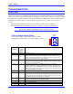
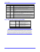
To enter Enhanced Mode, the Strobe Word must be set according to the table below.
ADC Strobe Word Value Description
$300FFF IGBT Temperature reported on phase B for each axis
$301FFF Bus Voltage reported on phase B for each axis
$3FDFFF Firmware Major version number in 00.00 (major.minor) format
$3FEFFF Firmware Minor version number in 00.00 (major.minor) format
WX:$C014 or I7m06
$3FFFFF Default mode
At present, the commands sent to axis one are active on all axes of the amplifiers, that is, if bus voltage
from axis one is requested, bus voltage from all axes on that amplifier will be received.
IGBT temperature:
For every 2.13 degrees Celsius there is an additional count at the ADC register, +1h. The baseline
temperature is set at 25°C, which means the ADC has a value of 21h. The maximum IGBT temperature
for the drive is 150° Celsius.
Bus Voltage:
For every 5.25Volts there is an additional count at the ADC register, +1h. The maximum Bus Voltage for
the 3U042 drive is 420VDC, (296VAC) before over voltage fault, which means the ADC has a value of
50h. The Shunt resistor turn on voltage is 388.5V, the value is 4Ah, and the turn off voltage is 367.5, a
value of 46h.
PWM Drive Command Structure 38