^1 HARDWARE MANUAL ^2 PMAC Mini PCI ^3 Programmable Multi-Axis Controller ^4 5xx-603712-xHxx ^5 April 26, 2010 Single Source Machine Control Power // Flexibility // Ease of Use 21314 Lassen Street Chatsworth, CA 91311 // Tel. (818) 998-2095 Fax. (818) 998-7807 // www.deltatau.
Copyright Information © 2010 Delta Tau Data Systems, Inc. All rights reserved. This document is furnished for the customers of Delta Tau Data Systems, Inc. Other uses are unauthorized without written permission of Delta Tau Data Systems, Inc. Information contained in this manual may be updated from time-to-time due to product improvements, etc., and may not conform in every respect to former issues. To report errors or inconsistencies, call or email: Delta Tau Data Systems, Inc.
REVISION HISTORY REV. 1 DESCRIPTION REVISIONS TO FLEX CPU BAUD RATE, PPS. 6 &21 DATE CHG APPVD 05/09/06 CP S. SATTARI 2 UPDATED ENCODER SETTING DESC., PPS. 6 & 20 01/30/09 CP S. MILICI 3 CORRECTED JUMPER LAYOUT E85-E87-E88, P. 25 04/26/10 CP S.
PMAC Mini PCI Hardware Reference Manual Table of Contents INTRODUCTION .....................................................................................................................................................1 Features ...................................................................................................................................................................1 Dimensions.........................................................................................................
PMAC Mini PCI Hardware Reference Manual E8 – E10: Synchronizing PMAC .........................................................................................................................20 E10A - E10C: Flash Firmware Bank Select.........................................................................................................20 E11-E14: Encoder Single Ended/Differential Select (Note: REV-103 and above).......................................................
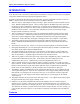
PMAC-Mini PCI Hardware Reference Manual INTRODUCTION The PMAC Mini PCI is an inexpensive, compact 2-axis version of the PMAC family. It can be used in a PC’s PCI slot as a half-sized board (230 mm, 9” long) or it can be used as a standalone using serial communications for setup and/or application control. Programs for the PMAC Mini PCI, both motion and PLC, are 100% compatible with other versions of PMAC. However, there are several features unique to the PMAC Mini PCI: 1.
PMAC Mini PCI Hardware Reference Manual • Motorola DSP 563xx Digital Signal Processor • Stand-alone operation • Two output digital-to-analog (DAC) converters • G-Code command processing for CNC • Four full encoder channels • Linear and circular interpolation • 16 general purpose I/O, OPTO-22 compatible • 256 motion programs capacity • Multiplexer port for expanded I/O • Asynchronous PLC program capability • Overtravel limit, home, fault amplifier enable flags • Rotating buffer for la
PMAC-Mini PCI Hardware Reference Manual HARDWARE SETUP The PMAC contains a number of jumpers (pairs of metal prongs) called E-points. These jumpers customize the hardware features of the board for a given application and must be set up appropriately. The following is an overview of the several PMAC jumpers grouped in appropriate categories. For a complete description of the jumper setup configuration, refer to the E-Point Descriptions section of this manual.
PMAC Mini PCI Hardware Reference Manual Option 6: Extended Servo Algorithm Firmware • Option 6 provides an Extended (Pole-Placement) Servo Algorithm firmware instead of the regular servo algorithm firmware. This is required only in difficult-to-control systems (resonances, backlash, friction, disturbances, changing dynamics). Part number: 306-00PMAC-OPT Option 6L: Special Lookahead Firmware • Option 6L provides a special lookahead firmware for sophisticated acceleration and cornering profile execution.
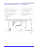
PMAC-Mini PCI Hardware Reference Manual Power Supply Configuration Jumpers (12-24V) A+V (pin 9) J9 (JEQU) E89 +12V E85 +5V A+15V E90 3 3 1 V/F +5V E100 1 Input Flags AENAs (EQUs) AGND AGND DACs E87 GND -12V P1 (Bus) / TB1 GND E88 A-15V JMACH1 E85, E87, E88: Analog Circuit Isolation Control – These jumpers control whether the analog circuitry on the PMAC is isolated from the digital circuitry, or electrically tied to it.
PMAC Mini PCI Hardware Reference Manual E34A-E37: Encoder Sample Clock – Only one of the jumpers E34A – E37 which select the encoder sample clock frequency, may be on in any configuration. The frequency must be high enough to accept the maximum true count rate (no more than one count in any clock period), but a lower frequency can filter out longer noise spikes. The anti-noise digital delay filter can eliminate noise spikes up to one sample-clock cycle wide.
PMAC-Mini PCI Hardware Reference Manual Board Reset/Save Jumpers E50: Flash-Save Enable/Disable Control – If E50 is on (default), the active software configuration of the PMAC can be stored to non-volatile flash memory with the SAVE command. If the jumper on E50 is removed, this SAVE function is disabled and the contents of the flash memory cannot be changed.
PMAC Mini PCI Hardware Reference Manual A wrong setting of these jumpers will damage the associated output IC. E101-E102: Motors 1-4 AENA/EQU Voltage Configure – The U37 driver IC controls the AENA and EQU signals of motors 1-4. With the default sinking output driver IC (ULN2803A or equivalent) in U44, these jumpers must connect pins 1 and 2 to supply the IC correctly.
PMAC-Mini PCI Hardware Reference Manual The Optional Dual-Ported RAM When the PMAC Mini PCI Option 2 is ordered, U20 is installed on-board at the factory. The DPRAM is located on the back of the board. See the PMAC User Manual for more information. LED Indicators The PMAC Mini PCI has two sets (front side and back) of three LED indicators. D9 and D9A (green) D10 and D10A (red) D19 and D19A (yellow) When the green LED is lit, this indicates that power is applied to the +5V input and it is good.
PMAC Mini PCI Hardware Reference Manual Y:$FFC2 J3 (JTHW) Outputs 0 1 2 3 4 5 6 7 SEL0 SEL1 SEL2 SEL3 SEL4 SEL5 SEL6 SEL7 THW Select 0 THW Select 1 THW Select 2 THW Select 3 THW Select 4 THW Select 5 THW Select 6 THW Select 7 (J3-4) (J3-6) (J3-8) (J3-10) (J3-12) (J3-14) (J3 16) (J3 18) Y:$FFC3 J5 (JOPTO) Inputs 0 1 2 3 4 5 6 7 MI1 MI2 MI3 MI4 MI5 MI6 MI7 MI8 Machine Input 1 Machine Input 2 Machine Input 3 Machine Input 4 Machine Input 5 Machine Input 6 Machine Input 7 Machine Input 8 (J5-15) (J5-13)
PMAC-Mini PCI Hardware Reference Manual Hardware Setup 11
PMAC Mini PCI Hardware Reference Manual OPTION 15 — VOLTAGE TO FREQUENCY CONVERTER When the PMAC Mini PCI Option 15 is ordered, the following components are installed on-board at the factory: Configuration as Analog Input with a 0-100 kHz Frequency Range Jumpers Setting Input 1 E110 OFF E111 ON E112 ON Input 2 E116 ON E117 ON E113 OFF E114 ON E115 ON E118 ON E119 ON Software configuration to be typed in the terminal window: WY$0724,$400722,1280 WY$0726,$400723,1280 I910=4 I915=4 M34->X:$0725,24
PMAC-Mini PCI Hardware Reference Manual Configuration as Analog Input with a 0-2 MHz Frequency Range Jumpers Setting Input 1 E110 OFF E111 OFF E34A ON E34 OFF E112 OFF Input 2 E116 ON E117 ON E113 OFF E114 OFF E115 OFF E118 ON E119 ON E34 - E37: Encoder Sampling Clock Frequency Control E35 OFF E36 OFF E37 OFF SCLK Clock Frequency 19.
PMAC Mini PCI Hardware Reference Manual 0-100 kHz Frequency Range and Pseudo-Feedback (no External Encoder Connected) Jumpers Setting Input 1 E110 ON E111 ON E112 ON Input 2 E116 ON E117 ON E113 ON E114 ON E115 ON E118 ON E119 ON 0-2 MHz Frequency Range and Pseudo-Feedback (no External Encoder Connected) Jumpers Setting Input 1 E110 ON E111 OFF E34A ON E34 OFF E112 OFF Input 2 E116 ON E117 ON E113 ON E114 OFF E115 OFF E118 ON E119 ON E34 - E37: Encoder Sampling Clock Frequency Control
PMAC-Mini PCI Hardware Reference Manual Option 15 — Voltage to Frequency Converter 15
PMAC Mini PCI Hardware Reference Manual SUGGESTED I/O M-VARIABLE DEFINITIONS General Purpose Inputs and Outputs M1->Y:$FFC4,0,1 M2->Y:$FFC4,1,1 M3->Y:$FFC4,2,1 M4->Y:$FFC4,3,1 M5->Y:$FFC4,4,1 M6->Y:$FFC4,5,1 M7->Y:$FFC4,6,1 M8->Y:$FFC4,7,1 M9->Y:$FFC4,0,8,U M11->Y:$FFC3,0,1 M12->Y:$FFC3,1,1 M13->Y:$FFC3,2,1 M14->Y:$FFC3,3,1 M15->Y:$FFC3,4,1 M16->Y:$FFC3,5,1 M17->Y:$FFC3,6,1 M18->Y:$FFC3,7,1 M19->Y:$FFC3,0,8,U ; ; ; ; ; ; ; ; ; ; ; ; ; ; ; ; ; ; Machine Machine Machine Machine Machine Machine Machine Mach
PMAC-Mini PCI Hardware Reference Manual Suggested I/O M-Variable Definitions 17
PMAC Mini PCI Hardware Reference Manual E-POINT JUMPER DESCRIPTIONS E0: Reserved for Future Use E-Point and Physical Layout Location E0 F1 Description Default Reserved for future use No jumper installed Warning: The jumper setting must match the type of driver IC, or damage to the IC will result.
PMAC-Mini PCI Hardware Reference Manual E3 - E6: Servo Clock Frequency Control The servo clock (which determines how often the servo loop is closed) is derived from the phase clock (see E29 - E33A and E98) through a divide-by-N counter. Jumpers E3 through E6 control this dividing function.
PMAC Mini PCI Hardware Reference Manual E8 – E10: Synchronizing PMAC E-Point and Physical Layout Location E8 C1 E9 C1 E10 E1 Description Jump pin 1-2 for NULL modem connection (DTR connects to DSR). Jump pin 2-3 for differential Phase signal (PHASE/). Jump pin 1-2 for NULL modem connection (DTR connects to DSR). Jump pin 2-3 for differential Servo signal (SERVO/). Jump pin 1-2 to select to receive external clocks CARD0.
PMAC-Mini PCI Hardware Reference Manual E17A - E17D: Amplifier-Enable/Direction Polarity Control E-Point and Physical Layout Location Description Default E17A A3 Jump 1-2 for high TRUE AENA1. Remove jumper for low TRUE AENA1. No jumper installed E17B A3 Jump 1-2 for high TRUE AENA2. Remove jumper for low TRUE AENA2. No jumper installed E17C A3 Jump 1-2 for high TRUE AENA3. Remove jumper for low TRUE AENA3. No jumper installed E17D A3 Jump 1-2 for high TRUE AENA4.
PMAC Mini PCI Hardware Reference Manual E29 - E33A: Phase Clock Frequency Control E29 E30 E31 E32 E33 E33A Phase Clock Freq. E98@1-2 Phase Clock Freq. E98@2-3 Default and Physical Layout E33A E33 E32 E31 E30 E29 ON OFF OFF OFF OFF OFF 2.26 kHz 1.13 kHz OFF ON OFF OFF OFF OFF 4.52 kHz 2.26 kHz OFF OFF ON OFF OFF OFF 9.04 kHz 4.52 kHz E31 ON OFF OFF OFF ON OFF OFF 18.07 kHz 9.04 kHz OFF OFF OFF OFF ON OFF 36.14 kHz 18.07 kHz OFF OFF OFF OFF OFF ON 72.28 kHz 36.
PMAC-Mini PCI Hardware Reference Manual E44 - E47: Communications Control Baud Rate Control E Points E44 E45 E46 E47 Baud Rate Standard CPU, 40 MHz Flash CPU (Opt 5A) 60 MHz Flash CPU (Opt 5B) Default and Physical Layout E44 E45 E46 E47 ON ON ON ON Disabled Disabled OFF ON ON ON 600 900 ON OFF ON ON 800* 1200 OFF OFF ON ON 1200 1800 ON ON OFF ON 1600* 2400 OFF ON OFF ON 2400 3600 ON OFF OFF ON 3200* 4800 OFF OFF OFF ON 4800 7200 ON ON ON OFF 6400* 9600 Opt 5B OFF ON ON OFF 9600 14400 Standard, Opt 5A O
PMAC Mini PCI Hardware Reference Manual E49: Serial Communications Parity Control E-Point and Physical Layout Location Description Default E49 E2 Jump pin 1 to 2 for no serial parity; remove jumper for odd serial parity. Jumper installed E50: EAROM Save Enable/Disable E-Point and Physical Layout Location Description Default E50 E2 Jump pin 1 to 2 to enable save to EAROM or flash memory; remove jumper to disable save to EAROM or flash memory.
PMAC-Mini PCI Hardware Reference Manual E85, E87, E88: Analog Power Source Configuration E-Point and Physical Layout Location Description E85 E3 Jump pin 1 to pin 2 to allow analog +V to come from digital side -- P1 or TB1 -- ties amplifier and PMAC Mini PCI power supply together, defeats opto-isolation. Remove jumper to keep analog +V separate from digital +12V. Note: If E85 is changed, E88 and E87 must also be changed Also see E90.
PMAC Mini PCI Hardware Reference Manual E89: Amplifier-Supplied Switch Pull-Up Enable E-Point and Physical Layout Location Description Default E89 A1 Jump pin 1 to 2 to allow A+V on J8 (JAUX) pin 13, to tie to A+15V on J11 (JMACH1) pin 59. Remove jumper to permit separate voltage supply from A+V for input flags (+12V to +24V for sinking drivers, 0V for sourcing drivers).
PMAC-Mini PCI Hardware Reference Manual E101 - E102: Amplifier Enable Output Configure E-Point and Physical Layout Location Description Jump pin 1 to 2 to apply A+15V from J11 pin 59 to pin 1 of E101, pin 3 of E102, and FAULT input flag return. This makes U44 AENA/ EQU / PULSE / DIR / FEFCO driver IC work from analog A+15V supply. Jump pin 2 to 3 to apply A+V (12-24V) from J8 pin 13 to pin 1 of E101, pin 3 of E102, and FAULT input flag return.
PMAC Mini PCI Hardware Reference Manual E116 - E119: V/F Converter Configuration (Voltage-to-Frequency Converter Option [OPT 15] Required) E-Point and Physical Layout Location E116 A3 E117 A3 E118 A3 Description Default Jump pin 1 to 2 to tie AENA1/DIR1 output to CHB3 input. Remove jumper to keep lines separate. Jump pin 1 to 2 to tie PULSE1 output to CHA3 input. Remove jumper to keep lines separate. No jumper installed Jump pin 1 to 2 to tie PULSE2 output to CHA4 input.
PMAC-Mini PCI Hardware Reference Manual E-Point Jumper Descriptions 29
PMAC Mini PCI Hardware Reference Manual MATING CONNECTORS This section lists several options for each connector. Choose an appropriate one for your application. J1 (JDISP)/Display Port 1. Two 14-pin female flat cable connector Delta Tau P/N 014-R00F14-0K0 T&B Ansley P/N 609-1441 2. 171-14 T&B Ansley standard flat cable stranded 14-wire 3. Phoenix varioface modules type FLKM14 (male pins) P/N 22 81 02 1 J2 (JEXP)/Expansion 1.
PMAC-Mini PCI Hardware Reference Manual Mating Connectors 31
PMAC Mini PCI Hardware Reference Manual CONNECTOR PINOUTS Headers J1 JDISP (14-Pin Header) Front View Pin # Symbol Function Description Notes 1 Vdd Output +5V Power Power Supply Out 2 Vss Common PMAC Common 3 Rs Output Read Strobe TTL Signal Out 4 Vee Output Contrast Adjust.
PMAC-Mini PCI Hardware Reference Manual J3 JTHW (26-Pin Header) Front View Pin # Symbol Function Description Notes 1 GND Common PMAC Common 2 GND Common PMAC Common 3 DAT0 Input Data-0 Input Data Input from Thumbwheel Switches 4 SEL0 Output Select-0 Output Scanner Output for reading TW Switches 5 DAT1 Input Data-1 Input Data Input from Thumbwheel Switches 6 SEL1 Output Select-1 Output Scanner Output for reading TW Switches 7 DAT2 Input Data-2 Input Data Input from Thumbwheel Switches 8 SEL2 Output Se
PMAC Mini PCI Hardware Reference Manual J4 JRS232 (10-Pin Header) Front View Pin # Symbol Function Description Notes 1 2 PHASE+ Bidirectional Receive/Transmit Phase Clock.
PMAC-Mini PCI Hardware Reference Manual J5 JOPT (34-Pin Connector) Continued Front View Pin # Symbol Function 27 28 29 30 31 32 33 MO3 GND MO2 GND MO1 GND +V Output Common Output Common Output Common I/O Description Machine Output 3 PMAC Common Machine Output 2 PMAC Common Machine Output 1 PMAC Common +V Power I/O Notes If Sinking Out Low True; If Source Out High True If Sinking Out Low True; If Source Out High True If Sinking Out Low True; If Source Out High True +V = +5V TO +24V +5V Out from PMAC
PMAC Mini PCI Hardware Reference Manual J8 JAUX (14-Pin Header) Front View Pin # Symbol Function Description Notes 1 2 3 4 5 6 7 WIPER1 Input 0-10V Analog Input 1, 2 WIPER2 Input 0-10V Analog Input 1, 2 AGND Common Analog/Flag Common AGND Common Analog/Flag Common EQU1/ Output Enc. 1 Position Compare 3 EQU2/ Output Enc. 2 Position Compare 3 AENA1/ Output Amp. 1 Enable/Direction 3,4,5 DIR1 8 AENA2/ Output Amp. 2 Enable/Direction 3,4,5 DIR2 9 PULSE1 Output Chan.
PMAC-Mini PCI Hardware Reference Manual J11 JMACH (60-Pin Header) Pin # Symbol Function Description 1 2 3 4 5 6 7 8 9 10 11 12 13 14 15 16 17 18 19 20 21 22 23 24 25 26 27 28 29 30 31 32 33 34 35 36 37 38 39 40 41 42 43 44 +5V +5V GND GND CHC3 CHC4 CHC3/ CHC4/ CHB3 CHB4 CHB3/ CHB4/ CHA3 CHA4 CHA3/ CHA4/ CHC1 CHC2 CHC1/ CHC2/ CHB1 CHB2 CHB1/ CHB2/ CHA1 CHA2 CHA1/ CHA2/ N.C. N.C. N.C. N.C. EQU1/ EQU2/ N.C. N.C. N.C. N.C. N.C. N.C. N.C. N.C.
PMAC Mini PCI Hardware Reference Manual J11 JMACH (60-Pin Header) -Continued Pin # Symbol Function Description Notes 45 DAC1/ Output Ana. Out Neg. 1 4,5 46 DAC2/ Output Ana. Out Neg. 2 4,5 47 AENA1/DIR1 Output Amp.-Ena/Dir. 1 6 48 AENA2/DIR2 Output Amp.-Ena/Dir. 2 6 49 FAULT1 Input Amp.-Fault 1 7 50 FAULT2 Input Amp.-Fault 2 7 51 MLIM1 Input Neg. End Limit 1 8,9 52 MLIM2 Input Neg. End Limit 2 8,9 53 PLIM1 Input Pos. End Limit 1 8,9 54 PLIM2 Input Pos.
PMAC-Mini PCI Hardware Reference Manual Terminal Block TB1 (JPWR) (4-Pin Terminal Block) Pin # Symbol Function Description Notes 1 GND Common Digital Ground 2 +5V Input +5V Supply Reference to digital ground 3 +12V Input +12V to +15V Supply Reference to digital ground 4 -12V Input -12V to -15V Supply Reference to digital ground This terminal block may be used as an alternative power supply connector if PMAC Lite is not installed in a PCbus. The +5V powers the digital electronics.
PMAC-Mini PCI Hardware Reference Manual JUMPERS AND CONNECTORS LAYOUT E1 E2 E3 E4 E5 E6 40 D1 D1 D3 D3 D3 D3 E7 E17A E17B E17C E17D E29 D1 F2 F2 F2 F2 E2 E30 E31 E32 E33 E33A E34A E34 E2 E2 E2 E2 E2 D2 D2 E35 E36 E37 E39 E44 E45 D2 D2 D2 A3 C1 C1 E46 E47 E48 E49 E50 E51 C1 C1 C1 C1 C1 C1 E66 E67 E68 E69 E70 E71 E2 E2 E2 E2 E2 E2 E85 E87 E88 E89 E90 E91 F3 F3 G3 G1 G1 E2 E92 E98 E100 E101 E102 E103 E2 D2 G1 F1 F1 A1 E104 E105 E110 E111 E112 E113 A3 A3 F1 F1 F1 E1 E114 E115 E116 E117 E118
PMAC-Mini PCI Hardware Reference Jumpers and Connectors Layout 41
Mini PMAC Hardware Reference Manual SCHEMATICS E44 E45 E46 E47 E48 E49 E50 E51 DAT6 DAT7 SEL0 SEL1 SEL2 SEL3 SEL6 SEL7 9 8 7 6 5 4 3 2 J1 (JDISP) J1 Vdd Vss RS Vee E R/W DB1 DB0 DB3 DB2 DB5 DB4 DB7 DB6 1 2 3 4 5 6 7 8 9 10 11 12 13 14 RS E R/W PA1 PA0 PA3 PA2 PA5 PA4 PA7 PA6 C147 optionally stuff zero ohm resistors or 74aca16245 INIT- .1UF C39 +5V 1 .1UF C40 E7 2 3 C150 RP50 3.
PMAC-Mini PCI Hardware Reference THIS DOCUMENT IS THE CONFIDENTIAL PROPERTY OF DELTA TAU DATA SYSTEMS INC. AND IS LOANED SUBJECT TO RETURN UPON DEMAND. TITLE TO THIS DOCUMENT IS NEVER SOLD OR TRANSFERRED FOR ANY REASON. THIS DOCUMENT IS TO BE USED ONLY PURSUANT TO WRITTEN LICENSE OR WRITTEN INSTRUCTIONS OF DELTA TAU DATA SYSTEMS INC. ALL RIGHTS TO DESIGNS AND INVENTIONS ARE RESERVED BY DELTA TAU DATA SYSTEMS INC. POSSESSION OF THIS DOCUMENT INDICATES ACCEPTANCE OF THE ABOVE AGREEMENT.
Mini PMAC Hardware Reference Manual +5V PHASE SERVO 9.8304Mhz 4.9152Mhz 2.4576Mhz 1.2288Mhz C61 0.001 mfd 0.1 mfd 19.6608Mhz R9 R10 1k 10k 1k int_vccio U21 1 2 3 4 5 6 7 8 9 10 11 12 13 14 15 16 17 18 19 20 21 22 23 24 25 26 27 28 29 30 31 32 33 34 35 36 37 38 39 40 41 42 43 44 45 46 47 48 49 50 51 52 53 54 55 56 57 58 59 60 conf_done tdo_pci VMECS- DPRBSYHOSTINT 0.22 mfd C75 INIT- 19.6608Mhz HENUSBOESRDSWRP1 BUSYR- pcibus_connector +5V +5V +5V +5V C76 4.7 mfd tant 16V (TANT) ad[0..
PMAC-Mini PCI Hardware Reference A+14V IN-B 13 ENC_A3 OUT-B IN-B ENA-B,D ENC_A4 11 OUT-D 8 IN-D GND IN-D MC34C86D CHA2- 15 CHA3- 14 CHA3+ 1 9 CHA4- CHA1CHB1CHC1- IN SIP SOCKET 1 CHA2+ CHB2+ CHC2+ CHA2CHB2CHC2- 1 2 2 A-14V 3 INSTALL FOR 0-TO-100Khz REMOVE FOR 0-TO-2Mhz 4 5 pul_ena 2.