
User's Manual


PMAC User Manual
106 Closing the Servo Loop
Finally, it provides a safer failure mode on loss of feedback. When a servo algorithm loses feedback, it
puts out a large torque command, which can cause runaway. However, when a commutation algorithm
loses its feedback, it will lock in like a stepper motor (for a synchronous motor) or at least fail to generate
significant torque (for an asynchronous – induction – motor). When both the servo and commutation
algorithms use the same feedback sensor connected over the same cable, both will lose feedback if one
does, creating a much more benign failure condition.
Pulse-and-Direction Amplifiers
Most stepper-motor amplifiers, and some stepper-replacement servo amplifiers, accept pulse and direction
inputs, where each pulse is a position increment. PMAC can generate this command format by passing its
analog command voltage through a voltage-to-frequency (V/F) converter such as the Acc-8D Option 2
board. In these systems, the true position loop is closed in the amplifier, as well as any velocity loops,
current loops, and motor commutation.
PMAC must close a false position loop for these motors using the electronically generated pulse train as
feedback. Since the output command is a frequency, or rate, of position change, it is effectively a velocity
command, and the loop can be tuned like that for a velocity-loop amplifier. The manual for Acc-8D Opt
2 V/F board has a list of optimal gain settings for each frequency version of the board.
Hydraulic Servo Amplifiers
Hydraulic servo valves create a pressure or force proportional to their command voltage by controlling
the orifice opening. Therefore, to the controller's servo loop it looks like a torque-mode amplifier
requiring derivative gain for stability. Some machine builders use the less expensive hydraulic
proportional valves. These valves have substantial crossover deadband compared to the servo valves.
This deadband can be compensated for to some extent with the PMAC Ix64 and Ix65 deadband
compensation, but the physical limitations of such an amplifier must still be realized.
Hydraulic motor amplifiers can be either torque-mode or velocity-mode, depending on whether they use a
velocity sensor and close a velocity loop themselves. To the PMAC servo loop, these amplifiers look just
like the amplifiers of the same type for electromagnetic motors.
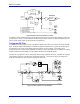
PID Servo Filter
The standard PMAC controller provides a PID position loop servo filter. Usually, this filter is sufficient
to control the system, and easily understandable as well, even for non-control specialists. The filter is
tuned by setting the appropriate I-variables for each motor.
How the PID Filter Works
The proportional gain (P — Ix30) provides the stiffness of the system; the differential gain (D — Ix31)
provides the damping for stability; the integral gain (I — Ix33) eliminates steady-state errors. Ix34
determines whether the integral gain is active all the time, or just during periods when the commanded
velocity is zero.