
User's Manual

PMAC User Manual
232 Synchronizing PMAC to External Events
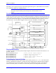
Compare Control Bits
There are three control bits to set up the format of the equals signals. The flag-latch control bit (M111 in
our example) controls whether the compare-equal signal is transparent (true only when the positions are
actually equal) or latched (true until actively reset). The signal is transparent if this control bit is zero,
and latched if the control bit is one. To clear a latched flag, take the control bit to zero, then back to one.
This compare-equal signal is always copied into the compare-equal flag (M116 in our example) that is
available for the PMAC internal use. If using this flag internally, make sure that the signal is latched
(M111=1), or it will be missed. For interrupting the host (edge-triggered), make the signal transparent.
The output-enable bit (M112 here) determines whether the compare-equal flag will be output on the EQU
line (1 enables). This must be set to use the signal either to interrupt the host or to trigger an external
event directly. The output-invert bit (M113 here) determines whether the EQUn output is high true or
low true (1 inverts to low true). For host-interrupt purposes, set this high true.
Interrupting the Host on a Compare-Equals
If using this EQUn line to interrupt the host, jumper the line to PMAC PC's 8259 Programmable Interrupt
Controller (PIC). The jumpers for this purpose are in the range E54 to E65 along the bottom edge of the
PMAC PC board. The output from this PIC must be jumpered to a PC interrupt line using one of the
jumpers E76-E84. Refer to the jumper tables and the Using the PMAC PC to Interrupt the Host
Computer section.
Directly Triggering External Action
To use the EQU lines to trigger external action from a PMAC PC, put a connector on the E-points (E53-
E65) that would jumper these signals to the interrupt controller (an IDC 26-pin connector can work
nicely). There is no other connector to bring these signals out. These signals must be buffered; the TTL
drivers for these outputs on PMAC PC are very weak.
On the PMAC Lite, PMAC VME and PMAC STD, there is a JEQU connector to bring out the Compare-
Equals outputs. These output are open-collector (sinking) outputs, rated to 24V and 100 mA. The
existing socketed driver IC may be replaced with a sourcing driver IC (UDN2981A).
Example:
The program COMPPULS.PMC in the Examples section shows how to use this feature to generate a very
rapid series of equals pulses on position intervals. As soon as PMAC detects that the previous compare
position has been reached, it clears the flag, loads the next compare position, and calculates the position
after that.
Offset from Motor Position
Encoder position is referenced to the position at the most recent power-on or reset, regardless of any
homing moves or offset commands done since then. To relate this encoder position to motor position,
one must know the offset between encoder zero and the homing-zero positions. Fortunately, this is
simply the position captured during the homing move, which PMAC stores for future use — in registers
Y:$0815 (#1, Y:$08D5 (#2), etc.
Note:
The position-compare feature uses encoder position, rather than motor or axis
position.
Synchronous M-Variable Assignment
Synchronous M-variable assignment statements allow outputs to be set and cleared synchronously with
the start of the next commanded move in the motion program. The output is synchronous with the
commanded position, not necessarily the actual position, which can be different due to following error.
These statements are discussed in detail in the Computational Features section of this manual.