
User's Manual

PMAC User Manual
58 Setting Up a Motor
Hardware Changes
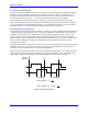
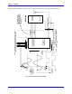
To implement this type of feedback properly, several settings in hardware and software must be changed
from the default. First, the socketed opto-isolators for the flag bits being used as interpolated bits must be
removed and replaced with hard-wired shunts so the signals are not delayed. This will tie the flag
circuitry to the digital circuitry. In this case, it is desirable to supply the remaining true flags from the
digital +12V circuitry (by moving the E90 jumper) and to tie the low ends to digital ground (GND); this
will retain the isolation between digital and analog circuitry.
Software Changes
In software, it is important to disable the digital delay filters on the encoder inputs of both the main
encoder, and the encoder matching the flag bits (even though that encoder is not actually used for this
function). This is done by setting Encoder I-Variable 1 (I901, I906, I911, etc.) to 1 for both of these
encoders.
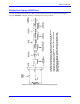
Parallel Position Feedback
PMAC can take parallel position feedback (e.g., from an absolute encoder, laser interferometer, or an
already converted analog signal) through its I/O expansion board (Accessory 14D/V). Each Acc-14D/V
board has 48 bits of input, so it may be connected to two parallel feedback devices of up to 24 bits each,
or one of over 24 bits. Up to six Acc-14D boards may be connected to a single PMAC. The parallel
feedback devices must provide straight binary data, not gray code. The PMAC internal registers will
extend the count automatically if the parallel device rolls over (unless the PMAC register is set up to roll
over as well).