
User's Manual


PMAC User Manual
Setting Up a Motor 65
For instance, to assign Motor #1 to the X-axis with 10,000 counts per unit, if the axis zero position should
be at the point where the absolute sensor reads 50,247 counts, then the axis position would be -50,247
counts when the sensor reads zero, so the axis definition statement would be: #1->10000X-50247.
Encoder Offset
If using resolvers for absolute power-on position information, subsequent position information comes
through the encoder counters, which are set to zero on power-on. For most purposes, this is transparent to
the user, but to use encoder registers directly, usually for position capture and compare functions, then
know the difference between the encoder-counter zero position, and the motor (resolver) zero position.
This value is kept in the Motor Encoder Position Offset Register [Y:$0815 (Motor 1), Y:$08D5 (Motor
2), etc.]. For an example of the use of this register, see the Storing the Home Position under Basic Motor
Moves section of this manual.
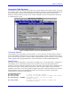
Encoder Conversion Table
The PMAC Executive Program for PC compatible computers has a special editing screen for the
conversion table that makes viewing it and changing it very easy. The detailed instructions here show
how to view and change the table even without the help of the executive program screens.
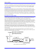
PMAC uses a multiple-step process to work with its feedback and master position information, and with
external time-base sources, to provide maximum power and flexibility. For most PMACs with quadrature
encoders, this process can be virtually transparent, with no need to worry about the details. However,
some basic understanding is needed of this conversion process to make the changes necessary to use other
types of feedback, to optimize the system, or to perform special functions.
The first step in the position and time-base conversion process is the hardware encoder counters with
associated timers, A/D registers, or accessory cards for parallel input. These work continually without
direct software intervention (although they can be configured through software). Beyond this point, the
process is software-controlled. At the start of each servo cycle, a servo interrupt signal is sent out to latch
all of the registers.
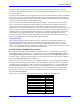
At this point, PMAC uses a software structure called the Encoder Conversion Table to process the
information in the latched registers. This table tells PMAC what registers to process, and how to process
them; it also holds the intermediate processed data.
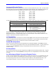
Ix03: Position Loop Feedback Address
Ix04: Velocity Loop Feedback Address
Ix05: Master Position Address
Ix93: Time Base Source Address
To Se r vo
Algorithms
Address
Encoder Conversion
Table
Data
Address
Data
PMAC Hardware
Registers
Conversion Instructions:
Process & Address
Processed
Feedback Data
RAM
Raw
Feedback
Data
Encoder Counters
& Timers, Latches, ADC's
Servo Address
I-Variables
Feedback
Data Signals
Figure 9 Encoder Conversion Table Process