
Reference Manual


PMAC-PCI Hardware Reference
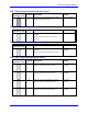
14 PMAC-PCI E-Point Jumper Descriptions
Main Board E-Point Jumper Descriptions
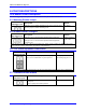
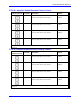
E0: Machine Output
E Point and
Physical Layout
Location Description Default
E0
A6
Jump pin 1 to 2
To provide use of 5V outputs
No jumper
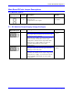
E1 - E2: Machine Output Supply Voltage Configure
E Point and
Physical Layout
Location Description Default
E1
A6
CAUTION
The jumper setting must match the type of driver IC,
or damage to the IC will result.
Jump pin 1 to 2 to apply +V (+5V to 24V) to pin 10
of U13 (should be ULN2803A for sink output
configuration) JOPTO machine outputs M01-M08.
Jump pin 2 to 3 to apply GND to pin 10 of U13
(should be UDN2981A for source output
configuration).
1-2 Jumper
installed
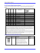
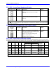
E2
A6
CAUTION
The jumper setting must match the type of driver IC,
or damage to the IC will result.
Jump pin 1 to 2 to apply GND to pin 10 of U13
(should be ULN2803A for sink output configuration).
Jump pin 2 to 3 to apply +V (+5V to 24V) to pin 10
of U13 (should be UDN2981A for source output
configuration).
1-2 Jumper
installed