
Reference Manual


PMAC-PCI Hardware Reference
PMAC-PCI E-Point Jumper Descriptions 17
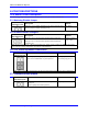
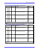
E22 - E23: Control Panel Handwheel Enable
E Point and
Physical Layout
Location Description Default
E22
A9 Jump pin 1 to 2 to obtain handwheel encoder
signal from front panel at J2-16 for CHB2
(ENC2-B).
No jumper
E23
A9 Jump pin 1 to 2 to obtain handwheel encoder
signal from front panel at J2-22 for CHA2
(ENC2-A).
No jumper
Note: With these jumpers ON, no encoder should be wired into ENC2 on JMACH1. Jumper E26 must
connect pins 1-2, because these are single-ended inputs. This function is unrelated to the encoder brought
in through Acc-39 on J2.
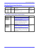
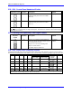
E28: Following Error/Watchdog Timer Signal Control
E Point and
Physical
Layout
Location Description Default
E28
C6 Jump pin 1 to 2 to allow warning following
error (Ix12) for the selected coordinate system
to control FEFCO/ on J8-57.
Jump pin 2 to 3 to cause Watchdog timer
output to control FEFCO/.
Low TRUE output in either case.
2-3 Jumper
installed
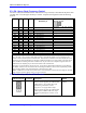
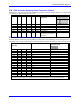
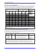
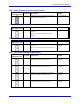
E29 - E33: Phase Clock Frequency Control
Jumpers E29 through E33 control the speed of the phase clock, and, indirectly, the servo clock, which is
divided down from the phase clock (see E3 - E6). No more than 1 of these 5 jumpers may be on at a time.
Phase Clock Frequency
E29 E30 E31 E32 E33
E98 Connects
Pins 1 and 2
E98 Connects
Pins 2 And 3
Default and
Physical
Layout
Location
ON OFF OFF OFF OFF 2.26 kHz 1.13 kHz
E29
A4
OFF ON OFF OFF OFF 4.52 kHz 2.26 kHz
E30
A4
OFF OFF ON OFF OFF 9.04 kHz 4.52 kHz
E31
A4
OFF OFF OFF ON OFF 18.07 kHz 9.04 kHz
E32
A4
OFF OFF OFF OFF ON 36.14 kHz 18.07 kHz
E33
A4
Note: If E40-E43 are not all ON, the phase clock is received from an external source through the J4 serial-
port connector, and the settings of E29 – E33 are not relevant.