
Reference Manual


PMAC-PCI Hardware Reference
20 PMAC-PCI E-Point Jumper Descriptions
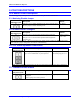
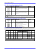
E49: Serial Communications Parity Control
E Point and
Physical Layout
Location Description Default
E49
C5 Jump pin 1 to 2 for NO serial parity. Remove
jumper for ODD serial parity.
Jumper installed
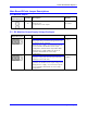
E50: Flash Save Enable/Disable
E Point and
Physical Layout
Location Description Default
E50
C5 Jump pin 1 to 2 to enable save to flash
memory.
Remove jumper to disable save to flash
memory.
Jumper Installed
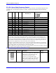
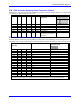
E51: Normal /Re-initializing Power-Up
E Point and
Physical Layout
Location Description Default
E51
B6 Jump pin 1 to 2 to re-initialize ON power-
up/reset;
Remove jumper for Normal power-up/reset.
No jumper
installed
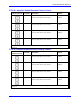
E54 - E65: Host Interrupt Signal Select
E Point and
Physical Layout
Location Description Default
E54
B7 Jump pin 1 to 2 to allow EQU8 to interrupt
host-PC at PMAC interrupt level IR7.
No jumper
installed
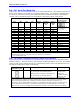
E55
B7 Jump pin 1 to 2 to allow EQU4 to interrupt
host-PC at PMAC interrupt level IR7.
No jumper
installed
E56
B7 Jump pin 1 to 2 to allow EQU7 to interrupt
host-PC at PMAC interrupt level IR7.
No jumper
installed
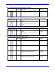
E57
B7 Jump pin 1 to 2 to allow EQU3 to interrupt
host-PC at PMAC interrupt level IR7.
No jumper
installed