
User's Manual


PMAC User Manual
Setting Up a Motor 81
Uses of Cross-Axis Compensation
The ability to have separate source and target motors for a table has several uses. The first is the
traditional compensation for imperfect geometry, as in a bowed leadscrew. For instance, on an XY table,
if the X-axis leadscrew is bowed, the Y-axis position should receive a correction as a function of X-axis
position. If motor #1 is the X-axis, and motor #2 is the Y-axis, the table holding this correction would
have motor #1 as the source motor, and motor #2 as the target motor.
A second use for cross-axis compensation is what is often known as the electronic cam. In this case, the
entire movement of the target motor is caused by the entries in the compensation table, not just the
corrections. This method of implementing electronic cam operation has two significant advantages over
The PMAC time-base following, the other method of creating electronic cams: the compensation table is
bidirectional – the master can turn in either direction – and it is absolute, so the phasing in is simply a
matter of homing the axes.
The time-base method, in which the motion program of the slave motors defines the motion, retains the
advantage of being able to change on the fly through math and logic in the program, and of second or
third-order interpolation between points, rather than the compensation table’s first-order interpolation.
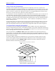
Two-Dimensional Leadscrew Compensation
It is possible to set up two-dimensional compensation tables on PMAC, where the compensation is a
function of the position of two motors. This makes it possible to set up planar compensation functions by
specifying a grid of compensation points. A 2D compensation table has two source motors and one target
motor. The target motor can be one of the source motors.
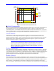
If the size parameter in the DEFINE COMP command that establishes the compensation table has a
decimal point, it is a 2D table, and the value before the decimal point specifies the number of columns, or
points for the first source motor; the value after the decimal point specifies the number of rows, or points
for the second source motor.
In operation, PMAC computes the compensation for a given location in the plane of the two source
motors as the weighted average of the four specified compensation values surrounding that location.
Refer to the description of the 2D DEFINE COMP command in the PMAC and PMAC2 Software
Reference Manual, 3A0-602705-363, for details.
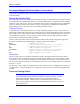
DEFINE COMP 20. 15, #1, #2, #3, 20000. 15000
Table columns
Table rows
1st source motor
2nd source motor
Target motor
1st motor span in counts
2nd motor span in counts
2D (Planar) Compensation Tables
z = f(x,y)
z
z
Figure 13 PMAC Compensation Tables