
User's Manual


PMAC User Manual
46 Input/Output: Connecting PMAC to the Machine
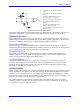
Amplifier Enable/Disable Use
These outputs are typically used as enable/disable lines for the amplifiers commanded by PMAC. This
control function is very important for safety reasons to make sure the amplifier can be completely shut
down when needed. (It is not a good idea to rely on a zero analog output voltage; offsets can easily build
up so that a zero command does not cause a stop. Analog output offset will manifest itself as creep in a
velocity-mode drive; on a lightly-loaded torque-mode drive, it can show up as high-speed runaway.)
Transition
When PMAC sees a fault signal from the amplifier, it will kill the motor automatically, taking the
amplifier-enable signal to the disabled state. Many amplifiers, when they are disabled for any reason, will
indicate a fault signal to the controller. PMAC permits an amplifier (changing the amplifier enable line
from disabled to enabled) to be enabled even when the amplifier shows a fault. However, in the PMAC
next error scan, which occurs in the background housekeeping task every few milliseconds, if the
amplifier still shows a fault, PMAC will disable that axis again. Refer to the Synchronizing PMAC to
External Events section of this manual.
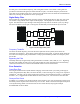
Sinking Drivers
The default drivers for these outputs are open-collector (sinking) circuits, requiring external pull-up
resistors. Typically, they can be connected directly to the cathode (negative end) of an opto-isolator input
on an amplifier. The ULN2803A ICs used are rated to 100 mA and 24V; internal diode protection
circuits in the IC limit the high voltage of the output to the analog positive supply voltage, usually +15V.
To defeat this protection and allow the outputs to be pulled above 15V, pin 10 of the driver IC must be
removed from the socket.
Sourcing Drivers
On newer hardware versions of PMAC, those with jumpers E101 and E102, a UDN2981A open-emitter
(sourcing) driver can be substituted for the standard sinking driver. This is done by exchanging the IC in
the socket and changing the placement of jumpers E101 and E102.
Polarity Control
Jumper E17 controls the polarity of these outputs. For PMAC PC, a jumper ON means low true enable
(default); a jumper OFF means high true enable. PMAC PC has a single jumper E17 for all four or eight
lines; PMAC Lite, -VME, and -STD have separate jumpers E17A to E17H for each channel. For PMAC
Lite, -VME, and –STD, a jumper OFF means low true enable (default for PMAC Lite and -VME); a
jumper ON means high-true enable (default for PMAC STD). The reason that the polarity is under
hardware, not software control is that it is important to make sure the amplifiers are properly disabled
even if the software fails.
Failsafe Polarity
With the default sinking drivers for the amplifier enable signals, using the low-true enable polarity (low
voltage — conducting — is enable; high voltage — non-conducting — is disabled) provides better
failsafe protection against loss of power supply. If either the +5V supply for the PMAC computational
section, or the +15V analog supply is lost, the amplifier will be disabled automatically, because the output
transistor will go into its non-conducting state. To use this failsafe protection without connecting a signal
of this polarity directly to the amplifier, use intermediate circuitry to change the signal format. With the
alternate sourcing drivers, the high-true enable polarity provides better failsafe protection.