
User's Manual


PMAC User Manual
66 Setting Up a Motor
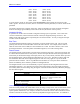
Conversion Table Structure
The Encoder Conversion Table has two columns, one in the X memory space of the processor, and one in
the Y memory space. The X-column holds the converted data, while the Y-column holds the addresses of
the source registers, and the conversion methods used on the data in each of those source registers.
Basically, set up the table by writing to the Y-column, and PMAC uses the Y-column data to fill up the
X-column each servo cycle.
Figure 10 Configure Encoder Conversion Table Editing Screen
Conversion Methods
The chart below lists the possible conversion formats. To do a conversion, the 8-bit format is matched
with a 16-bit address to fill the 24-bit Y-word in the conversion table. If there is more than one row for a
given conversion type, the other Y-words are further setup parameters for the conversion. The conversion
result is placed in the last (highest address) X-word, and the other X-words hold intermediate data.
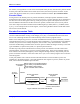
Adding Entries
For many conversion table entries – those with a second digit of x or y in the above table – setting bit 16
of the setup word to 1 means that the result of the conversion is not just from the specified source.
Instead, it is the sum of this entry and the entry above in the table. This permits the servo feedback to use
the sum of two sensors. (If the polarity of the sensors or their counters is opposite, this provides the
difference of the sensors. This can be useful for Doppler-type sensors, where the reference wave and the
shifted-frequency wave are fed into different counters, one counting up, the other counting down;
summing the two counters provides position.)
Example Setup Words:
WY:$720,$00C000 ;/T entry for encoder channel 1
WY:$721,$01C004 ;/T entry for encoder channel 2 summed with channel 1
WY:$722,$680721, $FFFFFF ;Intermediary entry for sum of encoder
;channel 1 and 2
WY:$724,00C008 ;/T entry for encoder channel 3 summed with
;Intermediary entry