^1 EZ SETUP SOFTWARE MANUAL ^2 PMAC2A-PC/104 ^3 EZ PMAC2A-PC104 Setup Manual ^4 4EZ-603670-xSxx ^5 September 24, 2004 Single Source Machine Control Power // Flexibility // Ease of Use 21314 Lassen Street Chatsworth, CA 91311 // Tel. (818) 998-2095 Fax. (818) 998-7807 // www.deltatau.
Copyright Information © 2003 Delta Tau Data Systems, Inc. All rights reserved. This document is furnished for the customers of Delta Tau Data Systems, Inc. Other uses are unauthorized without written permission of Delta Tau Data Systems, Inc. Information contained in this manual may be updated from time-to-time due to product improvements, etc., and may not conform in every respect to former issues. To report errors or inconsistencies, call or email: Delta Tau Data Systems, Inc.
EZ PMAC2A-PC-104 Setup Manual Table of Contents INTRODUCTION .......................................................................................................................................................1 Configuring PMAC ...................................................................................................................................................1 Getting More Information ..........................................................................................................
EZ PMAC2A-PC-104 Setup Manual Ix21 Motor x Jog/Home S-Curve Time ...............................................................................................................21 Ix23 Motor x Home Speed and Direction ...........................................................................................................22 Ix26 Motor x Home Offset ..................................................................................................................................22 Motor Home Commands ......
EZ PMAC2A-PC-104 Setup Manual INTRODUCTION PMAC, pronounced Pe’-MAC, stands for Programmable Multi-Axis Controller. It is a family of highperformance servo motion controllers capable of commanding up to 32 axes of motion simultaneously with a high level of sophistication. The PMAC2A-PC/104, member of the PMAC family, is a cost-effective 8-axis motion controller. The PMAC2A-PC/104 can be composed of three boards in a stack configuration.
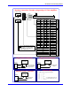
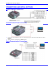
EZ PMAC2A-PC-104 Setup Manual Machine Connections Example: using analog ±10 Volts amplifiers 5V Power Supply Load Amplifier Motor Flags ± 15V Power Supply Encoder Motor #1 Motor #2 Motor #3 Motor #4 Pin # Pin # Pin # 5 7 9 1 3 6 8 10 1 3 19 21 23 2 4 20 22 24 2 4 Symbol HOMEn PLIMn MLIMn Flag_V Gnd Motor #1 Motor #2 Motor #3 Motor #4 Flags Sensor Connection 5-24 VDC Power Supply JMACH2 1 7 Flag_1_2_V + Pin # Pin # 1 3 5 7 9 11 13 15 29 31 33 35 2 4 6 8 10 12 14 16 30 32 34 36 1 3 17
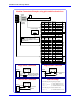
EZ PMAC2A-PC-104 Setup Manual Machine Connections Example: using pulse and direction drivers Driver Load Stepper Motor Flags Motor #1 Motor #2 Motor #3 Motor #4 5V Power Supply Note: The 5V external power supply is only required when PMAC is not installed in a PC/104 computer bus.
EZ PMAC2A-PC-104 Setup Manual 4 Introduction
EZ PMAC2A-PC-104 Setup Manual CONNECTIONS AND INITIAL SETTINGS Power Supplies Connections Communication Ports Connections • • Connect the host computer to only one communication port, either PC/104 bus, RS-232, USB or Ethernet. Select the port by clicking on the Device button.
EZ PMAC2A-PC-104 Setup Manual Installing and Running the Software Install the program by selecting the appropriate option on the CD-ROM provided or running the executable program downloaded from the Delta Tau website, and following the instructions on the screen. After the program is installed successfully, a new folder labeled QSPC104 will be present on the Windows© Start menu. The folder contains these items: • • • • EZ PMAC2A-PC/104 Setup Manual opens the electronic form of this manual.
EZ PMAC2A-PC-104 Setup Manual If Communications Cannot be Established 1. 2. 3. 4. 5. 6. Press the Re-Initialize button on the Communications Setup screen. Power-up PMAC with jumper E3 on the baseboard installed. Make sure the green LED in PMAC is lit; this will confirm that PMAC is properly powered with 5V. Press the Reset button in the middle of the screen. This will reset the memory to factory defaults. Turn off PMAC and remove the E3 jumper. Power-up PMAC and try communications again.
EZ PMAC2A-PC-104 Setup Manual The steps to configure PMAC are listed sequentially from top to bottom, but they can be called in any order. A simple terminal is provided to allow a direct communication with PMAC. However, during the initial setup process this is seldom necessary. If any I-Variable is changed on the terminal window, or if any reset command is issued, all motor status will change to red and the setup process must be repeated for each required motor.
EZ PMAC2A-PC-104 Setup Manual Power Supplies This page functions as a reminder that the ±15V should be connected before starting the setup process. Since PMAC requires a 5V power supply for operation and communications, the 5V power supply is assumed to be satisfactory at this point. Analog Amplifier Command Signals On this page, the output type for a particular motor is selected to be either analog ±10V or pulse-anddirection stepper outputs.
EZ PMAC2A-PC-104 Setup Manual • • ±10V input command differential signals Sinking enable input: the amplifier enables when the enable input is tied to ground. Since the DAC outputs are powered from PMAC, there is no need to turn-on the amplifier during this process. It is recommended that the amplifier and the machine are turned-off during this process. 1. 2. 3. 4. Select the motor to test its motor control signals. Slide the DAC value bar or input a DAC value from the keyboard.
EZ PMAC2A-PC-104 Setup Manual Since the pulse-and-direction stepper outputs are provided from PMAC, there is no need to turn on the stepper driver during this process. It is recommended that the stepper driver and the machine be turned off during this process. 1. Select the motor to test its motor control signals. 2. Slide the output value bar or input an output value from the keyboard. 3. Use an oscilloscope to observe the square signal generated from the pulse output.
EZ PMAC2A-PC-104 Setup Manual 4. The Encoder Capture indicator should change at every turn of the encoder shaft by the number of encoder counts per revolution. This indicates that the encoder C channel is operating properly. 5. Click Done if the encoder counts in the proper direction. If the encoder does not count: 1. Make sure the motor to which the encoder is connected is selected. 2. Press the Reset button and try again. 3.
EZ PMAC2A-PC-104 Setup Manual Polarity Test On this page, the motor polarity is checked. Correct polarity will show increasing encoder counts when PMAC outputs a positive command signal. This procedure requires the amplifier and motor being powered so, if possible, mechanically disengage the motor from the load. On this screen, the motor is controlled in open loop mode.
EZ PMAC2A-PC-104 Setup Manual 5. The open loop command can be output up until a limited time set on the screen. To disable this feature, set the Timer value to zero. The maximum value for this timer is 3600 seconds (one hour). At any time, press the Esc key to disable or kill all motors. However, it is recommended that there is easy access to an electrical switch that will shut down the amplifier and motor in case of failure or in an emergency.
EZ PMAC2A-PC-104 Setup Manual TUNING THE MOTORS The Tuning Procedure The tuning process is the definition of the PID loop parameters and the confirmation that PMAC can move the motors in closed loop with limited following error. The basic tuning procedure provided by the PMAC Quick Setup program might be limited in some cases to achieve an optimum tuning performance, but would allow, nevertheless, moving the motors in closed loop.
EZ PMAC2A-PC-104 Setup Manual 1. Select the motor that will perform the parabolic move. 2. Select the move distance in encoder counts based on the available travel distance and the encoder resolution. 3. Select the move time in milliseconds. This parameter determines how fast the move will be executed, resulting in a lower or higher velocity. Make sure the distance and time results in a kind of move close to those used in the actual application.
EZ PMAC2A-PC-104 Setup Manual MOTOR JOG COMMANDS From this page any activated motor can be moved in closed loop by means of Jog commands. Before jogging each motor, it is important to properly define all the move parameters. These parameters are explained in the following sections. Motor Safety I-Variables Warning: Setting Ix11 to zero (disabled) could lead to a dangerous motor runaway condition.
EZ PMAC2A-PC-104 Setup Manual Ix15 - Motor x Abort/Lim Deceleration Rate This variable, scaled in encoder counts per millisecond square, sets the deceleration rate used when a programmed motion is aborted either by the A Abort command or when a maximum position limit is reached. Ix16 - Motor x Maximum Velocity This variable, scaled in encoder counts per second, specifies the maximum allowed velocity for a motor performing a linear move commanded from a motion program.
EZ PMAC2A-PC-104 Setup Manual Rate vs Time: Programming the Maximum Acceleration Parameters The safety I-Variables Ix17 and Ix19 determine the maximum allowed acceleration for the motor x. These variables are programmed in the rate of encoder counts per millisecond square. However, the acceleration of a jog-programmed move is set in milliseconds as described above.
EZ PMAC2A-PC-104 Setup Manual Motor Jog Commands HomeZ This button resets the encoder counter, establishing a new zero reference for absolute jog move commands. Jog Neg This button jogs the selected motor continuously in the negative direction. Stop This button stops any jog command issued previously for the selected motor. Jog Pos This button jogs the selected motor continuously in the positive direction.
EZ PMAC2A-PC-104 Setup Manual HOME PROCEDURE Home commands allow establishing a physical point of reference for all programmed moves. If no home procedure is performed for a particular motor, the zero physical point of reference of that motor will be located at the point where it is found on power-up or reset.
EZ PMAC2A-PC-104 Setup Manual Ix23 Motor x Home Speed and Direction This variable sets the motor home search speed and direction in units of encoder counts per millisecond. Usually, the magnitude of this parameter is set the same as the jog velocity parameter Ix22. See the Motor Jog Commands section of this manual for more details. Ix26 Motor x Home Offset This is the relative position of the end of the homing cycle to the position at which the home trigger was made.
EZ PMAC2A-PC-104 Setup Manual MOTION PROGRAMS Coordinate Systems Definitions Before running a motion program, a coordinate system must be defined. A coordinate system consists of one or several motors that will be controlled in a coordinate fashion from a motion program. Each motor is linked to an axis letter with an optional scale factor. The scale factor allows, for example, programming each move in the motion program in units of inches, millimeters or simply revolutions of the motor.
EZ PMAC2A-PC-104 Setup Manual In all cases, if two times the S-curve acceleration parameter is greater than the linear acceleration parameter, then the overall acceleration time will be two times the S-curve acceleration time: If (2 x TS) > TA then TA = (2 x TS) Benefits of Using S-Curve Acceleration Profiles In an electric motor, the acceleration directly translates into torque and electrical current.
EZ PMAC2A-PC-104 Setup Manual Example: Motor 1 has been defined to be axis X with a scale factor of 1 X1000 F500 ; Move axis ‘X’ (motor 1) 1000 encoder counts with a ; velocity of 500 encoder counts per second If F is not included specifically in the program, the default value set in Ix89 will be used as the federate value. If the F parameter exceeds the value of the Ix98 variable and Ix98 is greater than zero, the value of Ix98 will be used as feedrate instead.
EZ PMAC2A-PC-104 Setup Manual X-3 ; Move axis X 3 length_units of distance in the ; opposite direction CLOSE Press Alt+X to exit the editor window: 7. To run this motion program, either press Run or Step. If Run is pressed, the program will run from start to finish without stopping. Otherwise, every time Step is pressed one line of the motion program will execute and the program will stop.
EZ PMAC2A-PC-104 Setup Manual PLC PROGRAMS PMAC is not only an excellent motion controller, but it can perform PLC operations. The 32 different PLC programs are similar to motion programs, but they run independently of motion programs and of other PLCs. Note: PLC0 is a special PLC that should be dedicated for operations that require fast execution. A large, time consuming PLC0 could in some cases, interfere with normal communications with the host computer.
EZ PMAC2A-PC-104 Setup Manual General-Purpose I/O and Analog Inputs Page This page shows the status of the JOPTO port on the ACC-1P board and the voltage that is input in the optional analog to digital converter inputs. Clicking on the I/O Port button on the PLC Programs page will show PMAC’s general-purpose digital I/O connector page. This page checks the PLC program example written above. 1. Set the PLCs and Simulated Inputs radio buttons to ON. 2. Click on the input switch for input MI1, pin 15.
EZ PMAC2A-PC-104 Setup Manual M0->Y:$C080,0 M1->Y:$C080,1 M2->Y:$C080,2 M3->Y:$C080,3 M4->Y:$C080,4 M5->Y:$C080,5 M6->Y:$C080,6 M7->Y:$C080,7 M8->Y:$C080,8 M9->Y:$C080,9 M10->Y:$C080,10 M11->Y:$C080,11 M12->Y:$C080,12 M13->Y:$C080,13 M14->Y:$C080,14 M15->Y:$C080,15 M32->X:$C080,0,8 M34->X:$C080,8,8 M40->X:$C084,0,24 M42->Y:$C084,0,24 ; ; ; ; ; ; ; ; ; ; ; ; ; ; ; ; ; ; ; ; Digital Output M00 Digital Output M01 Digital Output M02 Digital Output M03 Digital Output M04 Digital Output M05 Digital Output M06 D
EZ PMAC2A-PC-104 Setup Manual 30 PLC Programs
EZ PMAC2A-PC-104 Setup Manual BACKUP AND RESET PROCEDURES Backup Procedures Once PMAC is properly configured, save the software parameters in a backup file. On this page, select the parameters to save and the name of the file. To save the parameters on disk, press the Save button. To restore the parameters from a disk or read them from a previously saved backup file, press the Restore button. Note: With serial communications at 9600 baud rate, this procedure takes about one or two minutes.
EZ PMAC2A-PC-104 Setup Manual Reset PMAC to Last Saved Backup File Parameters Every time a backup file is created in the backup utilities page, a copy is saved under the BACKUP.CFG file name. With this command, PMAC can be reset at any time to the last saved configuration file, reading it from the BACKUP.CFG file. Reset PMAC to Last Memory Saved Parameters After a SAVE online command has been issued (see below), PMAC maintains its memory contents either with a battery or with a flash type memory.
EZ PMAC2A-PC-104 Setup Manual THE TERMINAL WINDOW AND UTILITY FUNCTIONS After PMAC has been configured properly, this terminal screen becomes the main operating screen from which every previously described function can be accessed easily. The terminal window has a rotating buffer that records the five last issued commands. These commands can be recalled through the arrow keys on the keyboard.
EZ PMAC2A-PC-104 Setup Manual This simple calculator has common arithmetic functions and an automatic decimal to hexadecimal conversion for every number entered. The hexadecimal field can be edited to obtain hexadecimal to decimal conversions as well. The Circle Function This function calculates the center and radius of any circular path, given the coordinates of three nonaligned points that belong to it. This is useful when programming PMAC in circular interpolation mode.