
User's Manual

EZ PMAC2A-PC-104 Setup Manual
2 Introduction
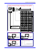
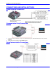
JMACH1
Motor #1
Pin #
Motor #2
Pin #
Motor #3
Pin #
Motor #4
Pin #
Symbol
1 2 1 2 +5V
3 4 3 4 GND
5 6 17 18 CHAn+
7 8 19 20 CHAn-
9 10 21 22 CHBn+
11 12 23 24 CHBn-
13 14 25 26 CHCn+
15 16 27 28 CHCn-
29 30 37 38 DACn+
31 32 39 40 DACn-
33 34 41 42 AENAn
35 36 43 44 FAULTn
47 FLT_FLG_V
48 GND
49 +12 to +15V
50 -12 to -15V
48 GND
3 GND
1 5V
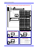
Motor #1
Pin #
Motor #2
Pin #
Motor #3
Pin #
Motor #4
Pin #
Symbol
5 6 19 20 HOMEn
7 8 21 22 PLIMn
9 10 23 24 MLIMn
1 1 2 2 Flag_V
3 3 4 4 Gnd
JMACH2
Amplifier
5V Power Supply
± 15V Power Supply
Flags
Encoder
Motor
Load
Note: The 5V and ±12V external
power supplies are only required
when PMAC is not installed in a
PC/104 computer bus.
Machine Connections Example: using analog ±10 Volts amplifiers
Flag_1_2_V
1
7
JMACH2
PLIM1
+-
5-24 VDC
Power Supply
Flags Sensor Connection
5 to 24 Volts normally
closed to ground NPN
sinking type sensor.
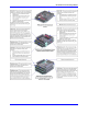
Flag_1_2_V
1
7
JMACH2
PLIM1
+-
5-24 VDC
Power Supply
Flags Switch Connection
Normally-Closed
Switch
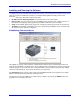
Software Setup
I-variables setup for using the DAC outputs:
I900 = 1001
I901 = 2
I902 = 3
I906 = 1001
I9n6 = 0 ; n = channel number from 1 to 8
Ix69 = 1024 ; x = motor number from 1 to 8
I10 = 1710933
FLT_FLG_V
47
35
JMACH1
FAULT-
+-
5-24 VDC
Power Supply
Amplifier Fault Connection
Connect to
amplifier