^1 HARDWARE REFERENCE MANUAL ^2 PMAC2A-PC/104 ^3 PMAC2A-PC/104 Hardware Reference Manual ^4 4xx-603670-xHxx ^5 September 22, 2004 Single Source Machine Control Power // Flexibility // Ease of Use 21314 Lassen Street Chatsworth, CA 91311 // Tel. (818) 998-2095 Fax. (818) 998-7807 // www.deltatau.
Copyright Information © 2003 Delta Tau Data Systems, Inc. All rights reserved. This document is furnished for the customers of Delta Tau Data Systems, Inc. Other uses are unauthorized without written permission of Delta Tau Data Systems, Inc. Information contained in this manual may be updated from time-to-time due to product improvements, etc., and may not conform in every respect to former issues. To report errors or inconsistencies, call or email: Delta Tau Data Systems, Inc.
PMAC2A PC104 Hardware Reference Manual Table of Contents INTRODUCTION .......................................................................................................................................................1 Board Configuration..................................................................................................................................................1 Base Version ............................................................................................................
PMAC2A PC104 Hardware Reference Manual DAC Output Signals ...........................................................................................................................................15 Pulse and Direction (Stepper) Drivers ...............................................................................................................15 Amplifier Enable Signal (AENAx/DIRn).............................................................................................................
PMAC2A PC104 Hardware Reference Manual J1 – USB Communications Port .........................................................................................................................39 J2 - Thumbwheel Multiplexer Port (JTHW Port) ...............................................................................................39 J7 - General-Purpose Digital Inputs and Outputs (JOPT Port).........................................................................
PMAC2A PC104 Hardware Reference Manual iv Table of Contents
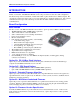
PMAC2A PC104 Hardware Reference Manual INTRODUCTION The PMAC2A PC/104 motion controller is a compact, cost-effective version of the Delta Tau’s PMAC2 family of controllers. The PMAC2A PC/104 can be composed of three boards in a stack configuration. The baseboard provides four channels of either DAC ±10V or pulse and direction command outputs. The optional axis expansion board provides a set of four additional servo channels and I/O ports.
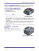
PMAC2A PC104 Hardware Reference Manual Option 12: Analog-to-Digital Converters Option 12 permits the installation of two channels of on-board analog-to-digital converters with ±10V input range and 12-bits resolution. The key component installed with this option is U20.
PMAC2A PC104 Hardware Reference Manual Acc-2P: Communications Board Without any options, the PMAC2A PC/104 communicates through the RS-232 serial interface using the optional Acc-3L flat cable. Only one method of communication is allowed at a time. Acc-2P Option 1A: USB Interface Option 1A it provides a 12 Mbit/sec USB interface allowing USB communications with the PMAC2A PC/104 motion controller.
PMAC2A PC104 Hardware Reference Manual 4 Introduction
PMAC2A PC104 Hardware Reference Manual BASE BOARD HARDWARE SETUP On the PMAC2 PC/104 baseboard, there are many jumpers (pairs of metal prongs) called E-points or Wpoints. Some have been shorted together; others have been left open. These jumpers customize the hardware features of the baseboard for a given application and must be setup appropriately. The following is an overview of the several jumpers grouped in appropriate categories.
PMAC2A PC104 Hardware Reference Manual CPU Jumper Configuration E15A-E15C: Flash Memory Bank Select Jumpers – The flash-memory IC in location U10 on the PMAC2A PC/104 base board has the capacity for eight separate banks of firmware, only one of which can be used at any given time. The eight combinations of settings for jumpers E15A, E15B, and E15C select which bank of the flash memory is used.
PMAC2A PC104 Hardware Reference Manual If this socketed resistor is configured as a pull-up resistor (by reversing the SIP pack in the socket), the two parallel 2.2 kΩ resistors act as a single 1.1 kΩ pull-up resistor, holding the line at +5V in the absence of an external signal. This configuration is required if complementary open-collector drivers are used; it is permissible for differential line-driver inputs.
PMAC2A PC104 Hardware Reference Manual 8 Baseboard Hardware Setup
PMAC2A PC104 Hardware Reference Manual ACC-1P HARDWARE SETUP On the Acc-1P, you will see many jumpers (pairs of metal prongs), called E-points. Some have been shorted together; others have been left open. These jumpers customize the hardware features of the Acc1P for a given application and must be setup appropriately. The following is an overview of the several jumpers grouped in appropriate categories.
PMAC2A PC104 Hardware Reference Manual The ‘-‘ inputs of each differential pair each have a hard-wired 2.2 kΩ resistor to +5V; each also has another 2.2 kΩ resistor as part of a socketed resistor pack that can be configured as a pull-up resistor to +5V, or a pull-down resistor to GND. If this socketed resistor is configured as a pull-down resistor (the default configuration), the combination of pull-up and pull-down resistors on this line acts as a voltage divider, holding the line at +2.
PMAC2A PC104 Hardware Reference Manual ACC-2P HARDWARE SETUP On the Acc-2P, there are many jumpers (pairs of metal prongs), called E-points. Some have been shorted together; others have been left open. These jumpers customize the hardware features of the Acc-2P for a given application and must be setup appropriately. The following is an overview of the several jumpers grouped in appropriate categories.
PMAC2A PC104 Hardware Reference Manual Resistor Packs Configuration Differential or Single-Ended Handwheel Encoder Selection The handwheel encoder differential input signal pairs to the PMAC have user-configurable pull-up/pulldown resistor networks to permit the acceptance of either single-ended or differential signals in one setting, or the detection of lost differential signals in another setting. The ‘+’ inputs of each differential pair each have a hard-wired 1 kΩ pull-up resistor to +5V.
PMAC2A PC104 Hardware Reference Manual MACHINE CONNECTIONS Typically, the user connections are actually made to terminal blocks that are attached to the JMACH connectors by a flat cable.
PMAC2A PC104 Hardware Reference Manual Flags Power Supply Each channel of PMAC has five dedicated digital inputs on the machine connector: PLIMn, MLIMn (overtravel limits), HOMEn (home flag), FAULTn (amplifier fault), and USERn. A power supply from 5 to 24V must be used to power the circuits related to these inputs. This power supply can be the same used to power PMAC and can be connected from the TB1 terminal block or the JMACH1 connector.
PMAC2A PC104 Hardware Reference Manual DAC Output Signals If PMAC is not performing the commutation for the motor, only one analog output channel is required to command the motor. This output channel can be either single-ended or differential, depending on what the amplifier is expecting. For a single-ended command using PMAC channel 1, connect DAC1+ (pin 29) to the command input on the amplifier. Connect the amplifier’s command signal return line to PMAC’s GND line (pin 48).
PMAC2A PC104 Hardware Reference Manual Amplifier Fault Signal (FAULT-) This input can take a signal from the amplifier so PMAC knows when the amplifier is having problems, and can shut down action. The polarity is programmable with I-variable Ix25 (I125 for motor 1) and the return signal is ground (GND). FAULT1- is pin 35. With the default setup, this signal must actively be pulled low for a fault condition.
PMAC2A PC104 Hardware Reference Manual For this driver, the internal resistor packs pull-down instead. With a UDN2981A driver IC, Jumper E1 must connect pins 2 and 3, and Jumper E2 must connect pins 2 and 3. Example: Standard configuration using the ULN2803A sinking (open-collector) output IC. Further software settings are required to configure this port. See the Software Setup section for details.
PMAC2A PC104 Hardware Reference Manual When used as non-multiplexed I/O, jumpers E7 and E8 on the Acc-2P board select the I/O lines direction of the JTHW connector. This allows configuring this port as all inputs, all outputs or half inputs and half outputs. If E7 is removed or E8 is installed then the multiplexing feature if the JTHW port cannot be used. Acc-1P or Acc-2P Handwheel Port (JHW / PD Port) This port provides an extra encoder input or a set of pulse and direction outputs.
PMAC2A PC104 Hardware Reference Manual Serial Port (JRS232 Port) For serial communications, use a serial cable to connect your PC's COM port to the J8 serial port connector present on the PMAC2A PC/104 baseboard. Delta Tau provides the Acc-3L cable for this purpose that connects the PMAC to a DB-9 connector. Standard DB-9-to-DB-25 or DB-25-to-DB-9 adapters may be needed for your particular setup.
PMAC2A PC104 Hardware Reference Manual Machine Connections Example: Using Analog ±10V Amplifier 20 Machine Connections
PMAC2A PC104 Hardware Reference Manual Machine Connections Example: Using Pulse and Direction Drivers Machine Connections 21
PMAC2A PC104 Hardware Reference Manual 22 Machine Connections
PMAC2A PC104 Hardware Reference Manual SOFTWARE SETUP Note: The PMAC2A PC/104 requires the use of V1.17 or newer firmware. There are few differences between the previous V1.16H firmware and the V1.17 firmware other than the addition of internal support for the Flex CPU design. Communications Delta Tau provides software tools that allow communicating with of the PMAC2A PC/104 board by either its standard RS-232 port or the optional USB or Ethernet ports.
PMAC2A PC104 Hardware Reference Manual If the CPU’s operational frequency has been determined by (a non-zero setting of) I46, the serial communications baud rate is determined at power-up/reset by variable I54 alone according to the following table: I54 Baud Rate I54 Baud Rate 0 1 2 3 4 5 6 7 600 900 1200 1800 2400 3600 4800 7200 8 9 10 11 12 13 14 15 9600 14,400 19,200 28,800 38,400 57,600 76,800 115,200 For a saved value of 0 for I46, the serial baud rate is determined by the combination of I54 a
PMAC2A PC104 Hardware Reference Manual Using Flag I/O as General-Purpose I/O Either the user flags or other not assigned axes flag on the base board can be used as general-purpose I/O for up to 20 inputs and 4 outputs at 5-24Vdc levels.
PMAC2A PC104 Hardware Reference Manual In order to properly setup the digital outputs an initialization PLC must be written scanning through once on power-up/reset, then disabling itself: OPEN PLC1 CLEAR M32=$FF M34=$0 M40=$FF00 M42=$FFFF DIS PLC1 ;BITS 0-8 are assigned as output ;BITS 9-16 are assigned as input ;Define inputs and outputs voltages ;All lines are I/O type ;Disable PLC1 (scanning through once on ;power-up/reset) CLOSE Note: After loading this program, set I5=2 or 3 and ENABLE PLC 1.
PMAC2A PC104 Hardware Reference Manual Thumbwheel Port Digital Inputs and Outputs The inputs and outputs on the thumbwheel multiplexer port of either the Acc-1P or the Acc-2P boards may be used as discrete, non-multiplexed I/O. In this case, these I/O lines can be accessed through Mvariables that are defined according to the setup of the address selection jumpers.
PMAC2A PC104 Hardware Reference Manual Analog Inputs Setup The optional analog-to-digital converter inputs are ordered either through Option-12 on the baseboard or Option-2 on the axes expansion board. Each option provides two 12-bit analog inputs with a ±10Vdc range. The M-variables associated with these inputs provided a range of values between +2048 and –2048 for the respective ±10Vdc input range. The following is the software procedure to setup and read these ports.
PMAC2A PC104 Hardware Reference Manual BASE BOARD HARDWARE REFERENCE SUMMARY The following information is based on the PMAC2A PC/104 board, part number 603670-100.
PMAC2A PC104 Hardware Reference Manual Board Layout 1 2 3 4 5 6 A 30 B C D E F Feature Location Feature Location Feature Location E0 E1 E2 E3 E4 E8 E9 E10 E11 E12 B3 B4 B4 C4 C4 B1 B1 E5 E5 E5 E13 E14 E15A E15B E15C E16 E18 E19 W1 E5 B3 E4 E4 E4 D1 D4 D4 E6 RP30 RP31 RP36 RP37 D1 D2 TB1 JRS232 JMACH1 JMACH2 E2 E2 E3 E3 A2 A3 B6 A2 F3 A4 Base Board Hardware Reference Summary
PMAC2A PC104 Hardware Reference Manual Connectors and Indicators J3 - Machine Connector (JMACH1 Port) The primary machine interface connector is JMACH1, labeled J3 on the PMAC. It contains the pins for four channels of machine I/O: analog outputs, incremental encoder inputs, amplifier fault and enable signals and power-supply connections. 1. 50-pin female flat cable connector T&B Ansley P/N 609-5041 2. Standard flat cable stranded 50-wire T&B Ansley P/N 171-50 3.
PMAC2A PC104 Hardware Reference Manual 32 Base Board Hardware Reference Summary
PMAC2A PC104 Hardware Reference Manual ACC-1P HARDWARE REFERENCE SUMMARY The following information is based on the Acc-1P board, part number 603671-100.
PMAC2A PC104 Hardware Reference Manual Board Layout 1 2 3 4 5 6 A 34 B C D E Feature Location Feature Location E0 E1 E2 E3 E4 E5 E6 E7 E16 D6 F1 C6 B2 B2 E4 E4 E5 E5 E5 D1 F6 A1 RP30 RP31 RP36 RP37 RP55 RP56 TB1 JMACH1 JMACH2 JHW / PD J7 J2 E2 E2 E3 E3 E4 E5 B6 F4 A4 A2 A3 E4 F Acc-1P Hardware Reference Summary
PMAC2A PC104 Hardware Reference Manual Connectors and Indicators J2 - Thumbwheel Multiplexer Port (JTHW Port) The Thumbwheel Multiplexer Port, or Multiplexer Port, on the JTHW connector has eight input lines and eight output lines. The output lines can be used to multiplex large numbers of inputs and outputs on the port, and Delta Tau provides accessory boards and software structures (special M-variable definitions) to capitalize on this feature.
PMAC2A PC104 Hardware Reference Manual 36 Acc-1P Hardware Reference Summary
PMAC2A PC104 Hardware Reference Manual ACC-2P HARDWARE REFERENCE SUMMARY The following information is based on the Acc-2P board, part number 603672-100.
PMAC2A PC104 Hardware Reference Manual Board Layout 1 2 3 4 5 6 A 38 B C D E Feature Location Feature Location E3 E4 E5 E6 E7 E8 E9 E10 RP22 RP23 F4 F3 F1 E6 D1 D1 D2 D2 E3 E3 D2 D6 D7 TB1 J1 JTHW JOPT JHW / PD J10 C6 A5 A6 B6 F6 F2 A2 F4 B5 F Acc-2P Hardware Reference Summary
PMAC2A PC104 Hardware Reference Manual Connectors and Indicators J1 – USB Communications Port This connector provides access to the USB communications feature ordered through Option-1A. See the Machine Connections section for details on using this port. J2 - Thumbwheel Multiplexer Port (JTHW Port) The Thumbwheel Multiplexer Port, or Multiplexer Port, on the JTHW connector has eight input lines and eight output lines.
PMAC2A PC104 Hardware Reference Manual 40 Acc-2P Hardware Reference Summary
PMAC2A PC104 Hardware Reference Manual BASE BOARD E-POINT JUMPER DESCRIPTIONS E0: Forced Reset Control E Point and Physical Layout Location Description E0 B3 Factory use only; the board will not operate with E0 installed. Default No jumper E1: Servo and Phase Clock Direction Control E Point and Physical Layout Location Description B4 Remove jumper for PMAC to use its internally generated servo and phase clock signals and to output these signals on the J8 serial port connector.
PMAC2A PC104 Hardware Reference Manual E4: CPU Frequency Select E Point and Physical Layout E4 Location Description Default C4 Remove jumper for 40 MHz operation (E2 OFF also) or for 60 MHz operation (E4 ON). Jump pin 1 to 2 for 80 MHz operation (E2 OFF).
PMAC2A PC104 Hardware Reference Manual E13: Power-Up/Reset Load Source E Point and Physical Layout Location E13 E5 Description Jump pin 1 to 2 to reload firmware through serial or bus port. Remove jumper for normal operation. Default No jumper E14: Watchdog Disable Jumper E Point and Physical Layout Location E14 B3 Description Jump pin 1 to 2 to disable Watchdog timer (for test purposes only). Remove jumper to enable Watchdog timer.
PMAC2A PC104 Hardware Reference Manual E18 – E19: PC/104 Bus Address E Point and Physical Layout E18 E19 Location Description Default D4 Jumpers E18 and E19 select the PC/104 bus address for communications according to the following table: No E18 jumper installed; Jumper E19 installed E18 E19 Address (Hex) Address (Dec) OFF OFF $200 512 OFF ON $210 528 ON OFF $220 544 ON ON $230 560 Note: Jumper E18 must be removed and jumper E19 must be installed for using either the Ethernet
PMAC2A PC104 Hardware Reference Manual ACC-1P E-POINT JUMPER DESCRIPTIONS E0: Reserved for Future Use E Point and Physical Layout Location Description Default E0 C6 For future use. No jumper E1 - E2: Machine Output Supply Voltage Configure E Point and Physical Layout Location Description E1 B2 Jump pin 1 to 2 to apply +V (+5V to 24V) to pin 10 of U7 (should be ULN2803A for sink output configuration) JOPTO Machine outputs M01-M08.
PMAC2A PC104 Hardware Reference Manual E5: Servo Gate Address Select E Point and Physical Layout Location Description E5 E5 Jump pin 1 to 2 to address Acc-1P channels at the regular addresses for channels 5 to 8. Jump pin 2 to 3 to address Acc-1P channels at the regular addresses for channels 5 to 8 plus $40.
PMAC2A PC104 Hardware Reference Manual ACC-2P E-POINT JUMPER DESCRIPTIONS E1: USB/Ethernet Micro-Controller Firmware Reload Enable E Point and Physical Layout Location Description Remove jumper to reload firmware on powerup reset.
PMAC2A PC104 Hardware Reference Manual E7- E10: Ports Direction Control E Point and Physical Layout Location E7 D1 Install jumper to make DATx lines inputs. No jumper to make DATx lines outputs. Jumper installed E8 D1 Install jumper to make SELx lines inputs. No jumper to make SELx lines outputs. No jumper E9 D2 Install jumper to make MOx lines inputs. No jumper to make MOx lines outputs. No jumper E10 D2 Install jumper to make MIx lines inputs. No jumper to make MIx lines outputs.
PMAC2A PC104 Hardware Reference Manual BASE BOARD CONNECTOR PINOUTS TB1 (JPWR): Power Supply (4-Pin Terminal Block) Top View Pin# Symbol Function Description Notes 1 GND Common Reference Voltage 2 +5V Input Positive Supply Voltage Supplies all PMAC digital circuits 3 +12V Input Positive Supply Voltage Ref to digital GND 4 -12V Input Negative Supply Voltage Ref to Digital GND This terminal block can be used to provide the input for the power supply for the circuits on the PMAC board when it is not in
PMAC2A PC104 Hardware Reference Manual J3 (JMACH1): Machine Port Connector (50-Pin Header) Top View 50 Pin# Symbol Function 1 2 3 4 5 6 7 8 9 10 11 12 13 14 15 16 17 18 19 20 21 22 23 24 25 26 27 28 29 30 31 32 33 34 35 36 37 38 39 +5V +5V GND GND CHA1 CHA2 CHA1/ CHA2/ CHB1 CHB2 CHB1/ CHB2/ CHC1 CHC2 CHC1/ CHC2/ CHA3 CHA4 CHA3/ CHA4/ CHB3 CHB4 CHB3/ CHB4/ CHC3 CHC4 CHC3/ CHC4/ DAC1 DAC2 DAC1/ DAC2/ AENA1/ AENA2/ FAULT1/ FAULT2/ DAC3 DAC4 DAC3/ Output Output Common Common Input Input Input Input Inpu
PMAC2A PC104 Hardware Reference Manual J3 JMACH1 (50-Pin Header) (Continued) Top View Pin# Symbol Function Description Notes 40 DAC4/ Output Analog Output Negative 4 4,5 41 AENA3/ Output Amplifier -Enable 3 42 AENA4/ Output Amplifier -Enable 4 43 FAULT3/ Input Amplifier -Fault 3 6 44 FAULT4/ Input Amplifier -Fault 4 6 45 ADCIN_1 Input Analog Input 1 Option-12 required 46 ADCIN_2 Input Analog Input 2 Option-12 required 47 FLT_FLG_V Input Amplifier Fault pull-up V+ 48 GND Input Analog Common 49 A+15V I
PMAC2A PC104 Hardware Reference Manual J4 (JMACH2): Machine Port Baseboard Connector (34-Pin Header) Pin# Symbol Function Description Front View Notes 1 FLG_1_2_V Input Flags 1-2 Pull-Up 2 FLG_3_4_V Input Flags 3-4 Pull-Up 3 GND Common Digital Common 4 GND Common Digital Common 5 HOME1 Input Home-Flag 1 10 6 HOME2 Input Home-Flag 2 10 7 PLIM1 Input Positive End Limit 1 8,9 8 PLIM2 Input Positive End Limit 2 8,9 9 MLIM1 Input Negative End Limit 1 8,9 10 MLIM2 Input Negative End Limit 2 8,9 11 USER1 Inp
PMAC2A PC104 Hardware Reference Manual ACC-1P CONNECTOR PINOUTS TB1 (JPWR): Power Supply (4-Pin Terminal Block) Top View Pin# Symbol Function 1 2 GND +5V Common Input Description Notes Reference Voltage Positive Supply Voltage Supplies all PMAC digital circuits 3 +12V Input Positive Supply Voltage REF to digital GND 4 -12V Input Negative Supply Voltage REF to digital GND This terminal block can be used to provide the input for the power supply for the circuits on the PMAC board when it is not in
PMAC2A PC104 Hardware Reference Manual J2 (JTHW): Multiplexer Port Connector (26-Pin Connector) Pin# Symbol Front View Function Description Notes 1 GND Common PMAC Common 2 GND Common PMAC Common 3 DAT0 Input Data-0 Input Data input from multiplexed accessory 4 SEL0 Output Select-0 Output Multiplexer select output 5 DAT1 Input Data -1 Input Data input from multiplexed accessory 6 SEL1 Output Select -1 Output Multiplexer select output 7 DAT2 Input Data -2 Input Data input from multiplexed accessory 8
PMAC2A PC104 Hardware Reference Manual J3 (JMACH1): Machine Port Connector (50-Pin Header) Top View Pin# Symbol Function 1 2 3 4 5 6 7 8 9 10 11 12 13 14 15 16 17 18 19 20 21 22 23 24 25 26 27 28 29 30 31 32 33 34 35 36 37 38 39 +5V +5V GND GND CHA5 CHA6 CHA5/ CHA6/ CHB5 CHB6 CHB5/ CHB6/ CHC5 CHC6 CHC5/ CHC6/ CHA7 CHA8 CHA7/ CHA8/ CHB7 CHB8 CHB7/ CHB8/ CHC7 CHC8 CHC7/ CHC8/ DAC5 DAC6 DAC5/ DAC6/ AENA5/ AENA6/ FAULT5/ FAULT6/ DAC7 DAC8 DAC7/ Output Output Common Common Input Input Input Input Input In
PMAC2A PC104 Hardware Reference Manual J3 JMACH1 (50-Pin-Header) (Continued) Top View Pin# Symbol Function Description Notes 40 DAC8/ Output Analog Out Negative 8 4,5 41 AENA7/ Output Amplifier-Enable 7 42 AENA8/ Output Amplifier -Enable 8 43 FAULT7/ Input Amplifier -Fault 7 6 44 FAULT8/ Input Amplifier -Fault 8 6 45 ADCIN_1 Input Analog Input 1 Option-2 required 46 ADCIN_2 Input Analog Input 2 Option-2 required 47 FLT_FLG_V Input Amplifier Fault pull-up V+ 48 GND Input Analog Common 49 A+15V Input D
PMAC2A PC104 Hardware Reference Manual J4 (JMACH2): Machine Port Connector (34-Pin Header) Pin# Symbol FLG_5_6_V FLG_7_8_V Function Front View Description Notes 1 Input Flags 5-6 Pull-Up 2 Input Flags 7-8 Pull-Up 3 GND Common Digital Common 4 GND Common Digital Common 5 HOME5 Input Home-Flag 5 10 6 HOME6 Input Home-Flag 6 10 7 PLIM5 Input Positive End Limit 5 8,9 8 PLIM6 Input Positive End Limit 6 8,9 9 MLIM5 Input Negative End Limit 5 8,9 10 MLIM6 Input Negative End Limit 6 8,9 11 USER5 Input User F
PMAC2A PC104 Hardware Reference Manual J7 (JOPTO): I/O Port Connector (34-Pin Connector) Front View Pin# Symbol Function Description 1 2 3 4 5 6 7 8 9 10 11 12 13 14 15 16 17 MI8 GND MI7 GND MI6 GND MI5 GND MI4 GND MI3 GND MI2 GND MI1 GND MO8 Input Common Input Common Input Common Input Common Input Common Input Common Input Common Input Common Output Machine Input 8 PMAC Common Machine Input 7 PMAC Common Machine Input 6 PMAC Common Machine Input 5 PMAC Common Machine Input 4 PMAC Common Machine
PMAC2A PC104 Hardware Reference Manual J8 (JHW) Handwheel Encoder Connector Pin# Symbol Function 1 2 GND HWA1+ / PUL1+ HWA1- / PUL1HWB1+ / DIR1+ HWB1- / DIR1HWA2+ / PUL2+ HWA2- / PUL2HWB2+ / DIR2+ HWB2- / DIR2+5V Common Input/Output Reference voltage HW1 Channel A or pulse output selected by jumpers E3 and E4 Input/Output HW 1 Channel A or pulse output selected by jumpers E3 and E4 Input/Output HW 1 Channel B or direction output selected by jumpers E3 and E4 Input/Output HW 1 Channel B or direc
PMAC2A PC104 Hardware Reference Manual 60 Acc-1P Connector Pinouts
PMAC2A PC104 Hardware Reference Manual ACC-2P CONNECTOR PINOUTS TB1 (JPWR): Power Supply (4-Pin Terminal Block) Top View Pin# Symbol Function Description Notes 1 GND Common Reference Voltage 2 +5V Input Positive Supply Voltage Supplies all PMAC digital circuits 3 +12V Input Positive Supply Voltage Ref to digital GND 4 -12V Input Negative Supply Voltage Ref TO Digital GND This terminal block can be used to provide the input for the power supply for the circuits on the PMAC board when it is not in a b
PMAC2A PC104 Hardware Reference Manual J2 (JTHW): Multiplexer Port Connector (26-Pin Connector) Pin# Symbol Front View Function Description Notes 1 GND Common PMAC Common 2 GND Common PMAC Common 3 DAT0 Input Data-0 Input Data input from multiplexed accessory 4 SEL0 Output Select-0 Output Multiplexer select output 5 DAT1 Input Data -1 Input Data input from multiplexed accessory 6 SEL1 Output Select -1 Output Multiplexer select output 7 DAT2 Input Data -2 Input Data input from multiplexed accessory 8
PMAC2A PC104 Hardware Reference Manual J7 (JOPT): I/O Port Connector (34-Pin Connector) Pin# Symbol Front View Function Description Notes 1 MI8 Input Machine Input 8 Direction selectable 2 GND Common PMAC Common 3 MI7 Input Machine Input 7 Direction selectable 4 GND Common PMAC Common 5 MI6 Input Machine Input 6 Direction selectable 6 GND Common PMAC Common 7 MI5 Input Machine Input 5 Direction selectable 8 GND Common PMAC Common 9 MI4 Input Machine Input 4 Direction selectable 10 GND Common PMAC Com
PMAC2A PC104 Hardware Reference Manual J8 (JHW) Handwheel Encoder Connector Pin# Symbol Function Description 1 2 3 4 5 6 7 8 9 10 GND HWA1+ / PUL1+ HWA1- / PUL1HWB1+ / DIR1+ HWB1- / DIR1HWA2+ / PUL2+ HWA2- / PUL2HWB2+ / DIR2+ HWB2- / DIR2+5V Common Input/Output Input/Output Input/Output Input/Output Input/Output Input/Output Input/Output Input/Output Output Reference voltage HW1 channel A or pulse output selected by jumpers E3 and E4 HW1 channel a or pulse output selected by jumpers E3 and E4 HW1 ch